BE1-40Q Setting and Testing
5-5
NOTE
With the test setup as specified, the current source phase angle setting simulates a
leading power factor angle, i.e.,
!
< 0.
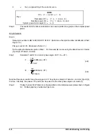
P
"
V
LL
3
(I
L
)cos
!
(4.6)
Q
"
V
LL
3
(I
L
)sin
!
(4.7)
Step 2.
Adjust the BE1-40Q Relay for the desired pickup value as specified by the generator
application or the test setup capabilities.
Step 3.
Adjust the TIME DELAY switches to a minimum value (e.g., 0.1, 0.2, or 0.3 seconds).
Step 4.
Adjust the voltage source to the nominal value of the sensing input as designated by the
second digit of the style number, at a leading phase angle of 150
!
.
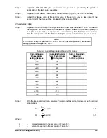
Characteristics Data
Step 1.
Adjust the current source phase angle for each of the values indicated in Table 5-3. Record
the magnitude of current required to receive each pickup indication. To measure pickup for
each phase angle setting, slowly increase the current magnitude from zero or a value less
than the pickup value until the PICKUP LED lights and an output contact operation occurs.
Table 5-3. Current Magnitudes Required for Pickup
Current Source
Phase Angle
Setting (Degrees)
Equivalent System
Power Factor Angle
(
!
) In Degrees
Current Magnitude
Required
for Pickup (Amps)
+20
-20
+30
-30
+40
-40
+50
-50
+60
-60
+70
-70
+80
-80
+90
-90
+100
-100
+110
-110
+120
-120
Step 2.
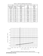
With the above recorded data, calculate P (watts) and Q (vars), as follows, for each recorded
pickup value.
Where:
V
LL
=
voltage measured in the test setup of Figure 5-2,
I
L
=
current measured in the test setup of Figure 5-2,
Содержание BE1-40Q
Страница 13: ...2 2 BE1 40Q Human Machine Interface Figure 2 1 Location of Controls and Indicators ...
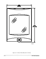
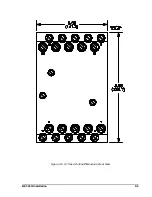
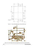
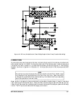
Страница 19: ...4 2 BE1 40Q Installation 2 02 01 D1427 01 Figure 4 1 S1 Case Outline Dimensions Front View ...
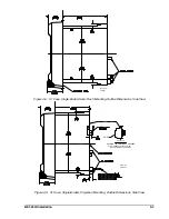
Страница 22: ...BE1 40Q Installation 4 5 Figure 4 6 S1 Case Outline Dimensions Rear View ...
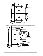
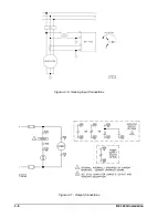
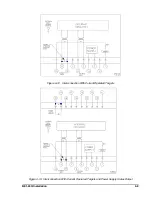
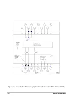
Страница 25: ...4 8 BE1 40Q Installation Figure 4 10 Sensing Input Connections Figure 4 11 Output Connections ...
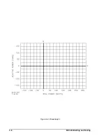
Страница 35: ...5 8 BE1 40Q Setting and Testing Figure 5 4 Blank Graph ...

