BE1-40Q Installation
4-7
NOTE
Be sure the relay case is hard-wired to earth ground with no smaller than 12 AWG copper
wire attached to the ground terminal on the rear of the relay case. When the relay is
configured in a system with other protective devices, it is recommended to use a separate
lead to the ground bus from each relay.
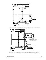
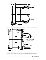
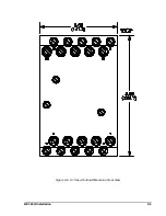
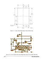
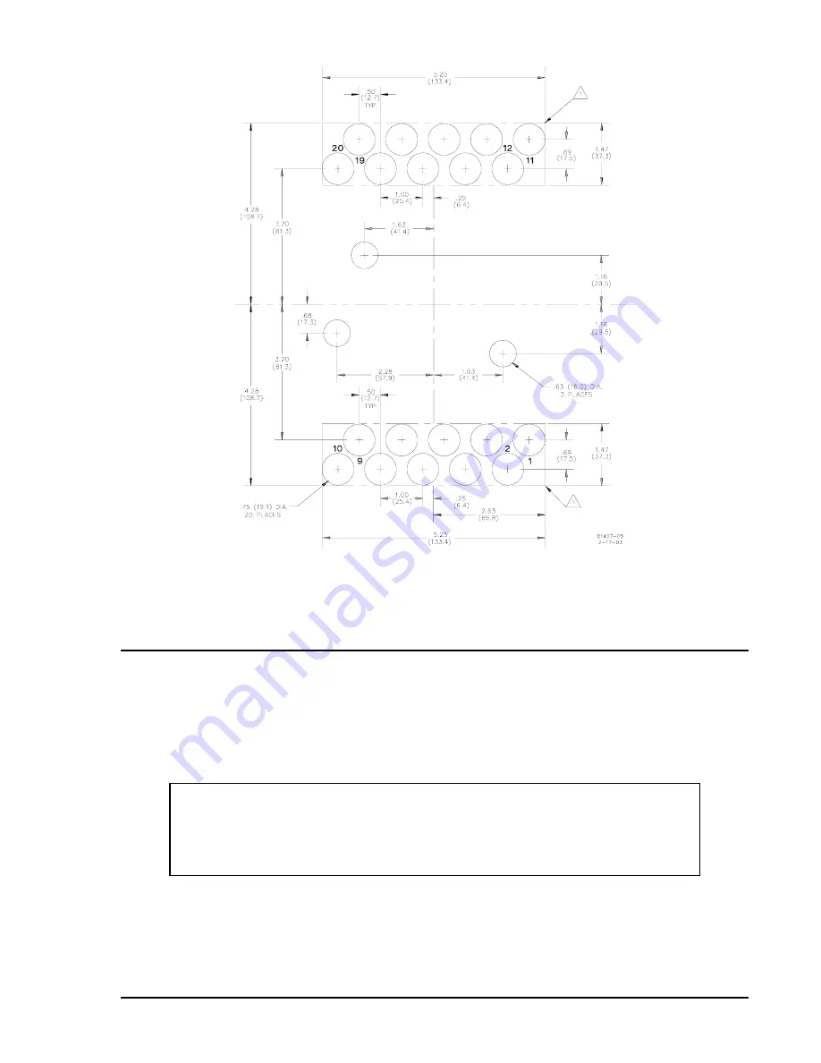
Figure 4-9. S1 Case, Double-Ended, Panel Drilling Diagram, Rear View (Projection Mounting)
CONNECTIONS
Incorrect wiring may result in damage to the relay. Except for the ground wire, connections should be made
with minimum wire size of 14 AWG. For the ground wire, refer to the following note. Typical sensing input
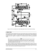
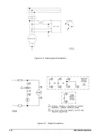
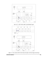
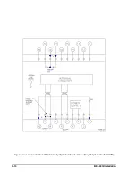
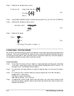
connections are shown in Figure 4-10. Typical output connections are shown in Figure 4-11. Internal wiring
diagrams are shown in Figures 4-12 through 4-14. All connections shown in this manual assume ABC
rotation.
Relay circuitry is connected to the case terminals by removable connection plugs (1 plug for 10-terminal
cases and 2 plugs for 20 terminal cases). Removal of the connection plug(s) opens the normally open trip
contact circuits and shorts the normally closed trip contact circuits before opening the power and sensing
circuits. The CT inputs are shorted when the plug(s) are removed.
Содержание BE1-40Q
Страница 13: ...2 2 BE1 40Q Human Machine Interface Figure 2 1 Location of Controls and Indicators ...
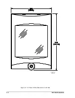
Страница 19: ...4 2 BE1 40Q Installation 2 02 01 D1427 01 Figure 4 1 S1 Case Outline Dimensions Front View ...
Страница 22: ...BE1 40Q Installation 4 5 Figure 4 6 S1 Case Outline Dimensions Rear View ...
Страница 25: ...4 8 BE1 40Q Installation Figure 4 10 Sensing Input Connections Figure 4 11 Output Connections ...
Страница 35: ...5 8 BE1 40Q Setting and Testing Figure 5 4 Blank Graph ...


