BE1-40Q Functional Description
3-3
Specifications, Table 1-1, and on the front panel tap range chart.
TAP Switch
The front panel TAP switch selects the pickup setting (in single-phase vars), depending on the position of
the HI/LOW RANGE switch, as shown in Table 1-1. The TAP switch selects the resistive burden value that
is placed across the output of the internal sensing input CT. The resistive burden establishes the scaling
of the internal signal that represents the input current value.
Transducer
The transducer consists of a multiplier and integrator. The multiplier and associated control circuits produce
an output that is representative of the product of the scaled current input and the scaled, phase-shifted
voltage input signal. The output waveform of the multiplier is an instantaneous value; therefore, the output
is integrated to develop a signal that represents the average var value. The integrator response time is a
function of the pickup multiple, as shown in Section 1,
Specifications.
Comparator
The signal representing the single-phase var value is compared with the pickup reference. When the
reference value is exceeded, the PICKUP LED indicator is illuminated and timing is initiated.
Timing
A definite time delay is initiated when the monitored var level exceeds the pickup reference. A calibrated
frequency generating circuit, in conjunction with counter circuits and the front panel TIME DELAY
thumbwheel switches, establishes the definite time delay interval.
Time delay is adjustable from 0.1 to 9.9 seconds in 0.1 second intervals. A setting of 00 enables
instantaneous (no intentional time delay) operation. Timing is instantaneously reset if the var level reduces
to less than the pickup setting.
For a complete description of timing accuracy, refer to
Specifications in Section 1.
Outputs
Defined by the style number, the output relay may have either a normally open (NO) or normally closed (NC)
configuration. The normally open output contact option is required when current operated targets are
desired.
In addition, an auxiliary output contact may be provided which is specified by style number as NO, NC, or
SPDT. If an auxiliary contact is provided, then the power supply status output is not available.
Targets
A magnetically-latching target indicator may be provided for the output contact as an option. This target is
actuated upon relay trip and may be either internally operated or current operated. An internally operated
target may be specified with either a normally open or normally closed output contact. When a current
operated target is desired, the output contact must be specified with a normally open configuration. The
current operated target requires a minimum of 0.2 amps flowing through the output relay contacts. The
target indicator must be reset with the manual target reset lever.
PUSH-TO-ENERGIZE OUTPUT Pushbutton
A small pushbutton switch may be provided as an option to allow testing the primary output contact and (if
present) the auxiliary output contact. To prevent accidental operation, the pushbutton is recessed behind
the front panel and is depressed by inserting a thin, non-conducting rod through an access hole in the front
panel.
Содержание BE1-40Q
Страница 13: ...2 2 BE1 40Q Human Machine Interface Figure 2 1 Location of Controls and Indicators ...
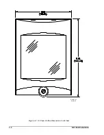
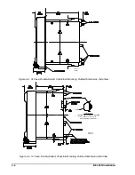
Страница 19: ...4 2 BE1 40Q Installation 2 02 01 D1427 01 Figure 4 1 S1 Case Outline Dimensions Front View ...
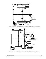
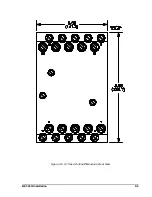
Страница 22: ...BE1 40Q Installation 4 5 Figure 4 6 S1 Case Outline Dimensions Rear View ...
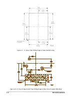
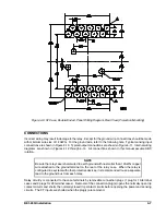
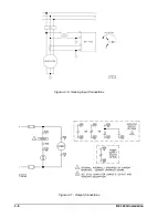
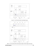
Страница 25: ...4 8 BE1 40Q Installation Figure 4 10 Sensing Input Connections Figure 4 11 Output Connections ...
Страница 35: ...5 8 BE1 40Q Setting and Testing Figure 5 4 Blank Graph ...


