4-10
BE1-25 Installation
NOTE
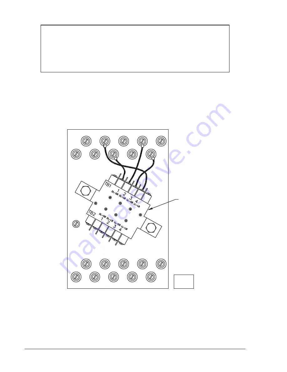
The Resistor Module shown in Figure 4-8 is required for BE1-25 Sync-Check relays,
Voltage Monitor option 2-C, 2-U, or 2-V.
When the relay is to be projection mounted (see Figure 4-3), the Resistor Module must be
removed prior to installation. Once the relay is installed, the Module is then attached to
the rear of the mounting panel. The external contact inputs are then wired to the Resistor
Module at TB2.
RESISTOR
MODULE
19
17
15
13
11
20
18
16
14
12
9
7
5
3
1
10
8
6
4
2
BE1-25
D999-005
3-10-92
Figure 4-9. Resistor Module Connections
www
. ElectricalPartManuals
. com