


1-4
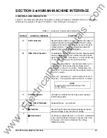
BE1-25 General Information
obtained by combining average voltage difference, phase angle limit, and line and bus live/dead voltage
limits. If a separate Voltage Monitor relay is supplied (Output option G or H), the NO contact must be in
series with the SYNC relay contact to perform the LL/LB and line not-overvoltage/bus not-overvoltage
enabling functions in Figure 1-2.
Option 2-R, 2-T, or 2-U (Phasor Voltage Difference)
Figure 1-4 may be used as an aid in formulating the voltage difference control settings. Note that the
center reference phasor (
V
B
) represents the monitored bus voltage, while the adjacent phasor (
V
L
)
represents the monitored line voltage. The voltage difference control (
∆
V) forms an area of acceptance
limit when rotated through 360 degrees. This allows either the voltage difference or the phase angle to be
selected, and the remaining value to be calculated.
Calculate the voltage difference (
∆
V) using the law of cosines. The equation is:
∆
V
V
V
V
V
L
B
L
B
=
+
− ⋅
⋅
⋅
(
cos )
2
2
2
1
2
θ
(1)
When
V
L
is tangent to the voltage difference circle, the
∆
V phasor is perpendicular to
V
L
at the phase
angle limit. Accordingly, the voltage difference or the phase angle can be calculated by equations 2 and 3,
respectively.
∆
V
V sin
B
=
θ
(2)
θ
∆
=
−
sin
V
V
1
B
(3)
where:
∆
V
= Voltage Difference
V
L
= Line Voltage
V
B
= Bus Voltage
θ
= Phase Angle
Note that the point where
V
L
is tangent to the voltage difference circle represents the most extreme
condition of
θ
for a closure. Assuming that a constant voltage difference exists, the following condition is
valid: If the magnitude of the line voltage decreases, the phase angle must also decrease to allow sync-
acceptance. Therefore, the minimum line voltage possible for sync-acceptance occurs at zero phase
angle.
www
. ElectricalPartManuals
. com