


BE1-25 General Information
1-3
LL ADJ
=100V
DL / OV ADJ
=40V
LINE
DEAD
LINE VOLTAGE
LIVE
135V (MAX)
100V
50V
10V (MIN)
2
LIVE LINE/
LIVE BUS
CONDITION
4
OV
135V (MAX)
100V
50V
10V (MIN)
P1004-36.vsd
01-29-01
BUS
1
DEAD LINE/
LIVE BUS
CONDITION
LIVE
DL / OV ADJ
=120V
LB ADJ
=35V
BUS VOLTAGE
60V FIXED MINIMUM VOLTAGE
LIMIT (LIVE LINE/LIVE BUS
CONDITION SYNC-CHECK
3
NOTES:
SYNC RELAY CONTACTS
CLOSED BY VOLTAGE MONITOR
SYNC-CHECK LOGIC ENABLED
2
1
LOGIC
4 OV EXCEEDED, SYNC-CHECK
TO ON PERMITS
LOGIC NOT ENABLED (SETTING
MODE SWITCH NO. 1 TO ON
AND CONDITION SWITCH NO. 1
FUNCTION ONLY)
OV)
3
3
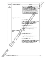
Figure 1-1. Voltage Monitor Acceptance Zones
Condition Switches
Five Condition Switches are located on the Voltage Monitor Card, each with two positions to select ON
(Down) and OFF (Up). When ON, Condition Switch No. 1 programs the relay to require recognition that
the line and bus are not in an overvoltage condition (NOT OV) before the SYNC output is allowed.
Condition Switches No. 2 through No. 5 modify the voltage monitor response according to a programmed
set of external conditions. The possible external conditions for each of these four switches are:
Switch 2.
Live Line/Live Bus (LL-LB)
Switch 3.
Dead Line/Live Bus (DL-LB)
Switch 4.
Live Line/Dead Bus (LL-DB)
Switch 5.
Dead Line/Dead Bus (DL-DB)
When a selected condition has been recognized, the voltage monitor circuit may be instructed to
immediately energize the Sync-Check output relay, or (if provided) the Voltage Monitor output relay. (See
Figure 1-1, Note 1.)
See Table 2-1, callout S, for a complete description and precautions on setting the Conditions Switches.
The location of the switches is shown in Figure 2-2.
Voltage Difference
A voltage monitor is available that checks the phasor or average voltage difference between the two
inputs. This can be used to prevent the closure of a generator breaker if the voltage difference is too great
(even if the phase angle and voltage level monitoring circuits indicate that proper closing conditions are
otherwise present).
The voltage difference option (included with option 2-A, 2-B, 2-C, 2-R, 2-T or 2-U) is typically used to
reduce the amount of possible system shock or transients when closing a breaker. This option compares
the voltage between line and bus against a selected limit, and initiates either an enable or an inhibit signal
for the sync-check logic, thereby narrowing the voltage across the breaker contacts (as compared to a
simple sync-check acting alone). Figure 1-2 shows closing zones obtained by combining phasor voltage
difference, phase angle limit, and line and bus live/dead voltage limits. Figure 1-3 shows closing zones
www
. ElectricalPartManuals
. com


