


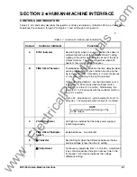


BE1-25 Human-Machine Interface
2-3
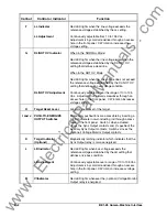
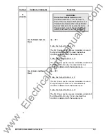
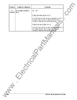
Callout
Control or Indicator
Function
N
DB/NOT OV
Indicator
When in the NORMAL Mode:
Red LED lights when the bus voltage is less than the
reference voltage established by the DB/NOT OV
setting that defines a dead bus condition.
When in the NOT OV Mode:
Red LED lights when the bus voltage does not exceed
the reference voltage established by the DB/NOT OV
setting that defines an overvoltage condition.
DB/NOT OV
Adjustment
Continuously adjustable over the range of 10 to 135
Vac. Adjustment is by small screwdriver through an
access hole in the front panel. CW rotation increases
the voltage setting.
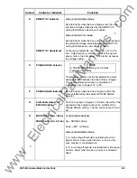
O
PHASE ANGLE Selector
NOTE
A PHASE ANGLE setting of 00 inhibits
operation of the relay.
Thumbwheel switches set the acceptable maximum
phase difference between the line and bus voltages.
This phase difference window is adjustable in 1
°
increments over a range of 01
°
to 99
°
.
P
PHASE ANGLE Indicator
Red LED lights when the phase angle is within the
limits established by the adjacent PHASE ANGLE
Selector.
Q
Switchable jumper for
EXPAND option
Position of jumper in Figure 2-2 controls the width of the
expanded phase angle window as a multiple of the
PHASE ANGLE setting. The two positions are X2 and
X3.
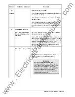
R
MODE Switch No. 1 (Bus)
MODE Switch No. 2 (Line)
For Both Mode Switches:
Up = NORMAL Mode;
Down = NOT OV Mode.
When in the NORMAL Mode:
(1) A high voltage threshold is established by front
panel controls, above which the bus (or line, as the
case may be) is considered live;
(2) A low voltage threshold is established by front panel
controls, below which the bus (or line) is considered
dead.
www
. ElectricalPartManuals
. com


