


1-6
BE1-25 General Information
V
L
V
B
P1000-37.vsd
01-29-01
θ
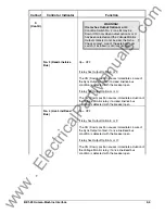
Figure 1-4. Closing Zone Calculation Diagram (Phasor Sensing)
V
P 1 0 0 4 - 3 9 . v s d
01-29-01
V B
L
V
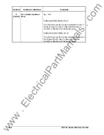
Figure 1-5. Closing Zone Diagram (Average Sensing)
Output Relay
The Voltage Monitor output relay option G or H provides additional supervision of the breaker closing
circuit, or provides an indication of the existing voltage conditions for the supervisory control system.
When a Voltage Monitor output relay is installed, the SYNC relay is no longer directly operable by voltage
monitor logic. However, the live line/live bus condition may be utilized to enable the Sync-Check function.
Detailed instructions and precautions for setting the Mode switches and Condition switches are provided
in Table 2-1, callouts R and S. The location of the switches is shown in Figure 2-2.
Voltage sensing connections are shown in Figure 4-8.
www
. ElectricalPartManuals
. com


