


BE1-25 Functional Description
3-3
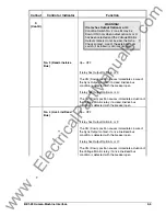
Table 3-1. Wide Range Power Supply Voltage Ranges
Power Supply
Style Chart
Identifier
Nominal Voltage
Voltage Range
Low Range
R
24 Vdc
12† to 32 Vdc
Mid Range
O, P
48, 125 Vdc,
120 Vac
24 to 150 Vdc,
90 to 132 Vac
High Range
T
125, 250 Vdc,
120, 240 Vac
62 to 280 Vdc,
90 to 270 Vac
† 14 Vdc required to start the power supply.
Relay operating power is developed by the wide range, isolated, low burden, flyback switching, solid state
power supply. Nominal
±
12 Vdc is delivered to the relay internal circuitry. Input (source voltage) for the
power supply is not polarity sensitive. A red LED turn ON to indicate that the power supply is functioning
properly.
Power Supply Status Output Option
The power supply status output relay (Option 3-6) has normally closed (NC) output contacts. The relay is
energized upon power-up, thus opening its contacts. The contacts will remain open as long as normal
relay operating voltage is maintained. However, if the power supply voltage falls below the requirements
for proper operation, the power supply status output relay de-energizes, thus closing the NC output
contacts.
Voltage Monitor Options
Voltage monitor options are shown in the lower portion of Figure 3-1, and described in the following
paragraphs.
Filters
Input voltages from bus and line are filtered and applied to the peak detectors or average detector
circuitry.
Peak Detectors (Option 2-R, 2-T, or 2-U)
Voltage difference (
∆
V) peak detectors measure the phasor voltage difference between line and bus, and
compare this difference against the setting of the front panel
∆
V control. If the detected difference is less
than the limit, the sync-check timer is enabled, and the front panel
∆
V LED is lighted.
Four additional peak detectors compare the sensed line and bus voltages with reference voltages
established by the front panel control settings. To illustrate operation, let us first consider the two upper
peak detectors, noting that they monitor the bus, and that one of them has its output inverted.
When the live bus (LB) peak detector determines the sensed bus voltage is above the threshold voltage, it
outputs a logic-high signal to the selection logic. But the DB/Not Overvoltage peak detector, because of
inversion, only provides a logic-high signal when sensed voltage is below the threshold, thereby identifying
either a dead bus (i.e., Mode Switch No. 1 is Up to select the NORMAL Mode), or a Not Overvoltage
condition (Mode Switch No. 1 is Down to select the NOT OV Mode).
The lower pair of peak detectors work in similar fashion to define line conditions, as determined by the
position of Mode Switch No. 2.
Average Detectors (Option 2-A, 2-,B or 2-C)
Voltage difference average detectors provide the same functionality as the peak detector inputs except
they measure the average voltage difference instead of phasor voltage difference.
Selection Logic
Voltage monitor selection logic is controlled by Mode and Condition switches or External Condition
Switches to produce the Voltage Monitor output.
www
. ElectricalPartManuals
. com