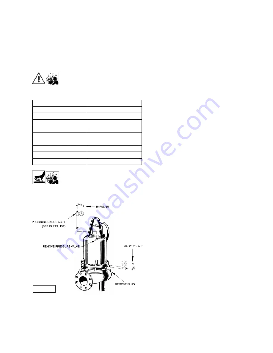
background image

9

FIGURE 2

Set unit upright and fi ll only until the motor, as viewed through 
the conduit box opening, is just covered and no more. Reas-
semble the O-ring (21), conduit box assembly (49) and cap 
screws (23), apply thread locking compound (38) to each cap 
screw (23) thread before installing. Torque cap screws (23) to 
15 ft., lb.

Seal Chamber -

 Refi ll chamber completely full with new cool-

ing oil per Table 1 or reuse the uncontaminated oil. (See parts 
list for amount.)

Important! - Do not overfi ll oil! 
Overfi lling of motor housing with oil can 
create excessive and dangerous hydraulic 
pressure which can destroy the pump and 

create a hazard. Overfi lling oil voids warranty.

TABLE 1 - COOLING OIL - Dielectric

SUPPLIER

GRADE

BP

Enerpar SE100

Conoco

Pale Paraffi n 22

Mobile

D.T.E. Oil Light

G & G Oil

Circulating 22

Imperial Oil

Voltesso-35

Shell Canada

Transformer-10

Texaco

Diala-Oil-AX

Woco

Premium 100

Caution! - Pressure builds up extremely 
fast, increase pressure by “tapping” air 
nozzle. Too much pressure will damage 
seal. Do Not exceed 10 P.S.I. in motor 

housing & 20-25 P.S.I. in seal chamber.

F-1.4) Pressure Test:
Motor Housing -

 Before checking the pump for leaks around 

the shaft seal, square rings, and cord inlet, the oil level should 
be full as described in section F-1.3. Remove pressure valve 
(26) from motor housing (1). 

Apply pipe sealant to pressure gauge assembly and tighten 
into pressure valve hole (See Fig. 2). Pressurize motor 
housing to 10 P.S.I. Use a soap solution around the sealed 
areas and inspect joints for “air bubbles”. If, after fi ve minutes, 
the pressure is still holding constant, and no “bubbles” are 
observed, slowly bleed the pressure and remove the gauge 
assembly. Replace the Pressure valve using a sealant. If the 
pressure does not hold, then the leak must be located.

Seal Chamber -

 Remove pipe plug (8) from Bearing Bracket 

(4) and check that seal chamber is full of oil. Apply pipe 
sealant to pressure gauge assembly and tighten into hole in 
bearing bracket (4). Pressurize seal chamber to 20-25 PSI 
and check for leaks as outlined above.

F-2) Impeller and Volute Service:
F-2.1) Disassembly and Inspection:

To clean out volute (43) or replace impeller (48), or replace 
wear ring (60), on High-Effi ciency pumps, disconnect power, 
remove hex nuts (7) and vertically lift motor and seal assembly 
from body (43). Clean out body if necessary. Clean and ex-
amine impeller (48), for pitting or wear and replace if required, 
inspect gasket (19) and replace if cut or damaged. If the impel-
ler (48) requires replacing, remove cap screw (46) and washer 
(45). The impeller is keyed onto the shaft with a square key 
(18) and to remove, pull impeller straight off the shaft using a 
wheel puller, if required. If the wear ring (60) on High-Effi ciency 
pumps require replacing, split the wear ring (60) and remove, 
be careful not to damage the volute. Before reinstalling, check 
the motor shaft and impeller bore for damage.

F-2.2) Reassembly:

To install wear ring (60) on High-Effi ciency pumps, fi rst apply 
retaining compound (42) to the bore of body (43) and then 
press wear ring (60) into bore of body (43) until seated. To 
install impeller (48), on all models, apply a thin fi lm of oil to 
motor shaft and slide impeller straight onto shaft, keeping 
keyways lined up. Drive key (18) into keyway. Locate washer 
(45), apply thread lock primer (such as Loctite® Primer T) let 
set per manufactures’ directions. Apply thread locking com-
pound to cap screw (46) threads, thread cap screw (46) into 
shaft and torque to 35 ft. lb. Rotate impeller to check for bind-
ing. Position gasket (19) on volute fl ange and install impeller 
and motor housing over studs and onto volute (43). Apply 
thread locking compound (38) to threads of each stud (20). 
Thread nut (7) onto stud (20) and torque to 24 ft. lb. Check 
for free rotation of motor and impeller.

F-3) Motor and Bearing Service
F-3.1) Disassembly and Inspection:

To examine or replace the motor (47) and bearings (2) and 
(5), disassemble pump, volute and impeller (as outlined in 
paragraph F-2.1) and disassemble seal plate and shaft seal 
(as outlined in paragraph F-4.1). Drain oil from motor as out-
lined in paragraph F-1.3.

Position unit upright, using blocks to avoid resting unit on 
shaft. After removal of cable and box assembly (49) from 
motor housing (1), remove cable lead wires from motor 
lead wires and moisture and temperature sensors wires (if 
equipped) from control cable by unscrewing connectors (22) 
and (32). The wiring connections should be noted to insure 
correct connections when reassembling. Remove cap screws 
(6) and hex nuts (7). 

Содержание BARNES 4DSE-HL Series

Страница 1: ...he right to change product without prior written noti cation 420 Third Street 83 West Drive Bramton Piqua Ohio 45356 Ontario Canada L6T 2J6 Phone 937 778 8947 Phone 905 457 6223 Fax 937 773 7157 Fax 9...

Страница 2: ...8 20 CROSS SECTION Fig 13 21 EXPLODED VIEW Fig 114 15 22 23 PARTS LIST 24 25 RETURNED GOODS POLICY 26 WARRANT START UP REPORT WARRANTY REGISTRATION SPECIAL TOOLS AND EQUIPMENT INSULATION TESTER MEGGER...

Страница 3: ...insert ngers in pump with power connected Always wear eye protection when working on pumps Make sure lifting handles are securely fastened each time before lifting DO NOT operate pump without safety d...

Страница 4: ...Hardware 300 series stainless steel CORD ENTRY 40 Ft 12 1m Cord Epoxy sealed housing with secondary pressure grommet for sealing and strain relief SPEED 1150 1750 RPM 60Hz nominal UPPER BEARING Desig...

Страница 5: ...300 series stainless steel CORD ENTRY 40 Ft 12 1m Cord Epoxy sealed housing with secondary pressure grommet for sealing and strain relief SPEED 1150 1750RPM 60Hz nominal UPPER BEARING Design Single Ro...

Страница 6: ...g should be as short as possible Both a check valve and a shut off valve are recommended for each pump being used The check valve is used to prevent back ow into the sump Excessive back ow can cause o...

Страница 7: ...575 3 1150 E 5 4 34 4 10 4 SOW 0 75 4DSE7596L 7 5 200 230 3 1150 B D 24 4 21 3 107 8 124 10 4 SOW 0 75 0 75 4DSE7546L 7 5 460 3 1150 D 10 6 62 0 10 4 SOW 0 75 2 99 4DSE7556L 7 5 575 3 1150 D 8 48 49 6...

Страница 8: ...t a preventive mainte nance program is recommended and suggested to include the following checks 1 Inspect motor and seal chambers for oil level and contamination and repair as required per section F...

Страница 9: ...ler 48 or replace wear ring 60 on High Ef ciency pumps disconnect power remove hex nuts 7 and vertically lift motor and seal assembly from body 43 Clean out body if necessary Clean and ex amine impell...

Страница 10: ...ille washers and shims 10 and 11 in upper end bell Position upper motor end bell aligning holes and thread cap screws into bearing bracket 4 Torque to 16 ft lb Place all motor leads above the motor Po...

Страница 11: ...ce facing bearing bracket 4 slide rotating member 12D onto shaft using seal pusher until lapped faces of 12D and 12E are together See Figure 6 It is extremely important to keep seal faces clean during...

Страница 12: ...s outlined in paragraph F 2 1 Then remove screws 52 and adapter 53 Reassemble by placing gasket 54 and adapter 53 on volute 43 with screws 52 Reassemble volute onto pump assembly as outlined in paragr...

Страница 13: ...uired 7 Shipping instructions 8 Billing Instructions G 2 PART NUMBER The part number consists of a six 6 digit number which ap pears in the catalog A one or two letter suf x may follow this number to...

Страница 14: ...impeller for freedom of operation security and condition Clean impeller and inlet of any obstruction 9 Loosen union slightly to allow trapped air to escape Verify that turn off level of switch is set...

Страница 15: ...15 FIGURE 10 4DSE L Pump Series...

Страница 16: ...16 FIGURE 11 4DSE L Pump Series...

Страница 17: ...17 4DSE L Pump Series FIGURE 12...

Страница 18: ...1 036852 Gasket Rubber 20 6 033824 Stud 3 8 16 x 2 00 21 1 051937 Square Ring Buna N 22 5 016405 Splice Cap All Except 5Hp 1Ph 7 5Hp 200V 3Ph 030148 Splice Cap For 5Hp 1Ph 7 5Hp 200V 3Ph 23 4 1 529 1...

Страница 19: ...9 00 Dia 084894TQ 8 88 Dia 084894TR 8 75 Dia 5HP STD 084894TS 8 62 Dia 084894TT 8 50 Dia 084894TU 8 38 Dia 084894TV 8 25 Dia 084894TW 8 12 Dia 084894TX 8 00 Dia 084894TY 7 88 Dia 084894TZ 7 75 Dia 08...

Страница 20: ...met For 4DSE5024L ONLY 49E 1 Control Cable Not Sold Separately 49F 1 051448 Gland Nut 49G 1 021531 Friction Ring 49H 1 066871 Grommet 49J 1 030169 Ground Screw 10 32 x 625 Lg Stainless 52 8 24 113 1 F...

Страница 21: ...21 4DSE HL High Ef ciency Pump Series FIGURE 13...

Страница 22: ...22 4DSE HL High Ef ciency Pump Series FIGURE 14...

Страница 23: ...23 4DSE HL High Ef ciency Pump Series FIGURE 15...

Страница 24: ...ainless 19 1 036852 Gasket Rubber 20 6 033824 Stud 3 8 16 x 2 00 21 1 051937 Square Ring Buna N 22 5 016405 Splice Cap All Except 5Hp 1Ph 10Hp 030148 Splice Cap For 5Hp 1Ph 10Hp 23 4 1 529 1 Hex Hd Sc...

Страница 25: ...5Ft 072700XL 100Ft 072700XP 125Ft 072700XS 150Ft 072700XV 175Ft 072700XY 200Ft 49A 1 Power Cable Not Sold Separately 49B 1 051447 Gland Nut 1 072559 Gland Nut For 4DSE5024HL 10HP 49C 2 051450 Friction...

Страница 26: ...o Insure That Employees Will Not Be Exposed To Health Hazards In Handling Said Material All Applicable Laws And Regulations Shall Apply IMPORTANT WARRANTY REGISTRATION Your product is covered by the e...

Страница 27: ...27 NOTE...

Страница 28: ...guarantees in the nature of performance speci cations furnished in addition to the foregoing material and workmanship warranties on a product manufactured by us if any are subject to laboratory tests...

Страница 29: ...m Does impeller turn freely by hand Yes No Condition of equipment Good Fair Poor Condition of cable jacket Good Fair Poor Resistance of cable jacket Good Fair Poor Resistance of cable and pump motor m...

Страница 30: ...ction Pump Off L1 L2 L2 L3 L3 L1 Voltage supply at panel line connection Pump On L1 L2 L2 L3 L3 L1 Amperage Load connection Pump On L1 L2 L3 FINAL CHECK Is pump seated on discharge properly Check for...

Страница 31: ...CITY STATE ZIP MODEL NO SERIAL NO PART NO BRAND IMPORTANT WARRANTY REGISTRATION Your product is covered by the enclosed Warranty Complete the Warranty Registration Form and return to Crane Pumps Syst...

Страница 32: ...CRANE PUMPS SYSTEMS INC WARRANTY SERVICE GROUP 420 THIRD STREET PIQUA OHIO 45356 U S A FOLD HERE AND TAPE DO NOT STAPLE PLACE STAMP HERE...

Отзывы: