page 99
page 99
page 99
page 99
page 99
475 A CRL
800-00167
CAT 330 CRAWLER LOWER MAINTENANCE
CAT 330 CRAWLER LOWER MAINTENANCE
CAT 330 CRAWLER LOWER MAINTENANCE
CAT 330 CRAWLER LOWER MAINTENANCE
CAT 330 CRAWLER LOWER MAINTENANCE
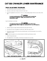
TRACK ADJUSTMENT PROCEDURE
TRACK ADJUSTMENT PROCEDURE
TRACK ADJUSTMENT PROCEDURE
TRACK ADJUSTMENT PROCEDURE
TRACK ADJUSTMENT PROCEDURE
1. Drive the machine forward in the direction of the idlers.
2. Stop when one track pin is directly over the front carrier roller.
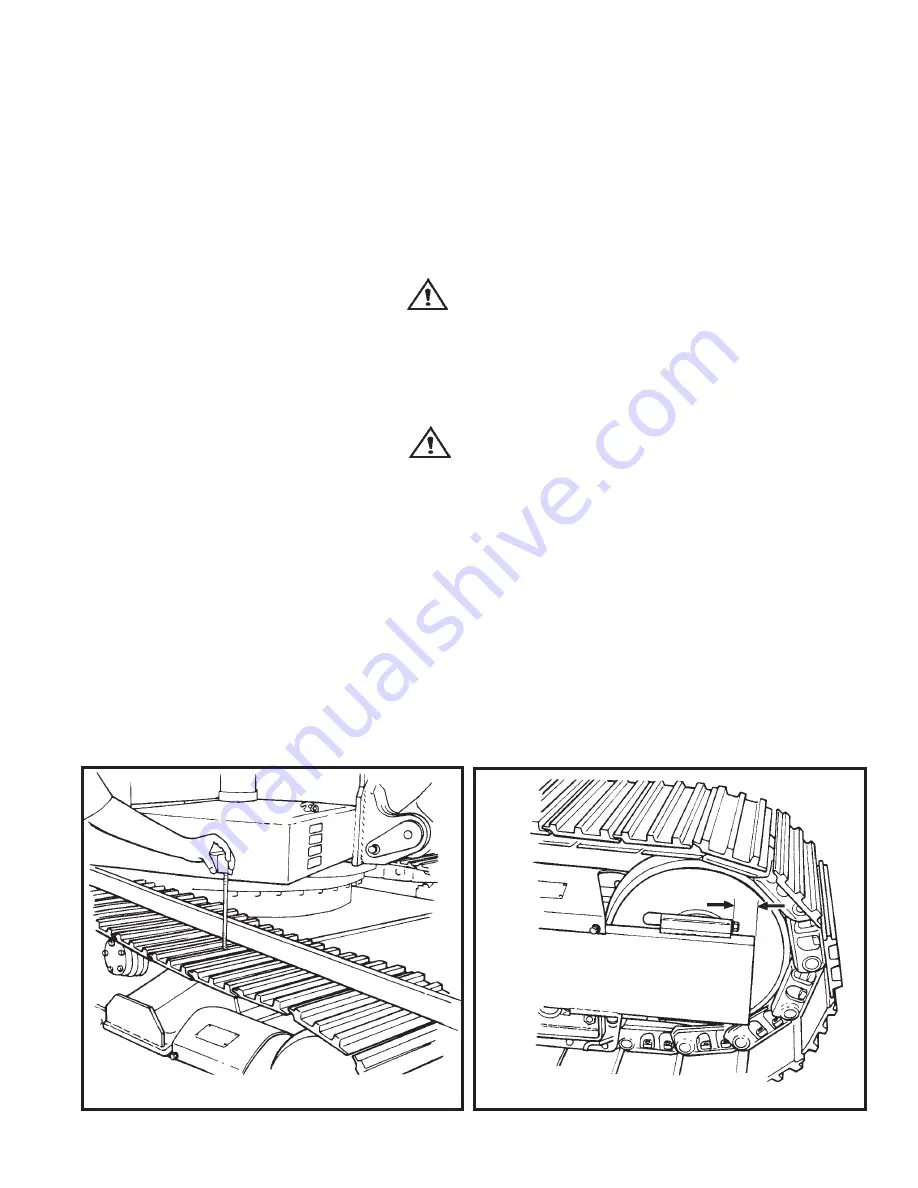
3. The correct adjustment is 25 to 40 mm (1.0 to 1.5 in.) of sag halfway between the front carrier roller and the
idler.
WARNING
WARNING
WARNING
WARNING
WARNING
To prevent possible personal injury, never visually inspect the relief valve
To prevent possible personal injury, never visually inspect the relief valve
To prevent possible personal injury, never visually inspect the relief valve
To prevent possible personal injury, never visually inspect the relief valve
To prevent possible personal injury, never visually inspect the relief valve
to see if grease is coming out. Always look at the track to see if it has
to see if grease is coming out. Always look at the track to see if it has
to see if grease is coming out. Always look at the track to see if it has
to see if grease is coming out. Always look at the track to see if it has
to see if grease is coming out. Always look at the track to see if it has
become loose or tight.
become loose or tight.
become loose or tight.
become loose or tight.
become loose or tight.
Open the relief valve one turn only.
CAUTION
CAUTION
CAUTION
CAUTION
CAUTION
If the dimension between the end of the track roller frame and the flange
If the dimension between the end of the track roller frame and the flange
If the dimension between the end of the track roller frame and the flange
If the dimension between the end of the track roller frame and the flange
If the dimension between the end of the track roller frame and the flange
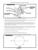
on the idler hub (as shown in Figure 2) is less than 25 mm (1 in.), do not adjust the
on the idler hub (as shown in Figure 2) is less than 25 mm (1 in.), do not adjust the
on the idler hub (as shown in Figure 2) is less than 25 mm (1 in.), do not adjust the
on the idler hub (as shown in Figure 2) is less than 25 mm (1 in.), do not adjust the
on the idler hub (as shown in Figure 2) is less than 25 mm (1 in.), do not adjust the
track.
track.
track.
track.
track.
4. Remove the plate covering the fill and relief valves on the track roller frame.
5. If the track is too loose, add grease in the fill valve until the track sag is correct.
6. If the track is too tight, turn the relief valve counterclockwise one turn and let grease come out until the
adjustment is correct.
NOTE
NOTE
NOTE
NOTE
NOTE: It will be necessary to move the machine back and forth to get the pressure equal.
7. Check the adjustment again.
8. If the adjustment is correct, tighten the relief valve and replace the cover plate.
Figure 1 - Measuring Track Looseness
Figure 1 - Measuring Track Looseness
Figure 1 - Measuring Track Looseness
Figure 1 - Measuring Track Looseness
Figure 1 - Measuring Track Looseness
Figure 2 - Measuring Track Looseness
Figure 2 - Measuring Track Looseness
Figure 2 - Measuring Track Looseness
Figure 2 - Measuring Track Looseness
Figure 2 - Measuring Track Looseness

