


R5909934 /00
E2 Lite and EC-40
75
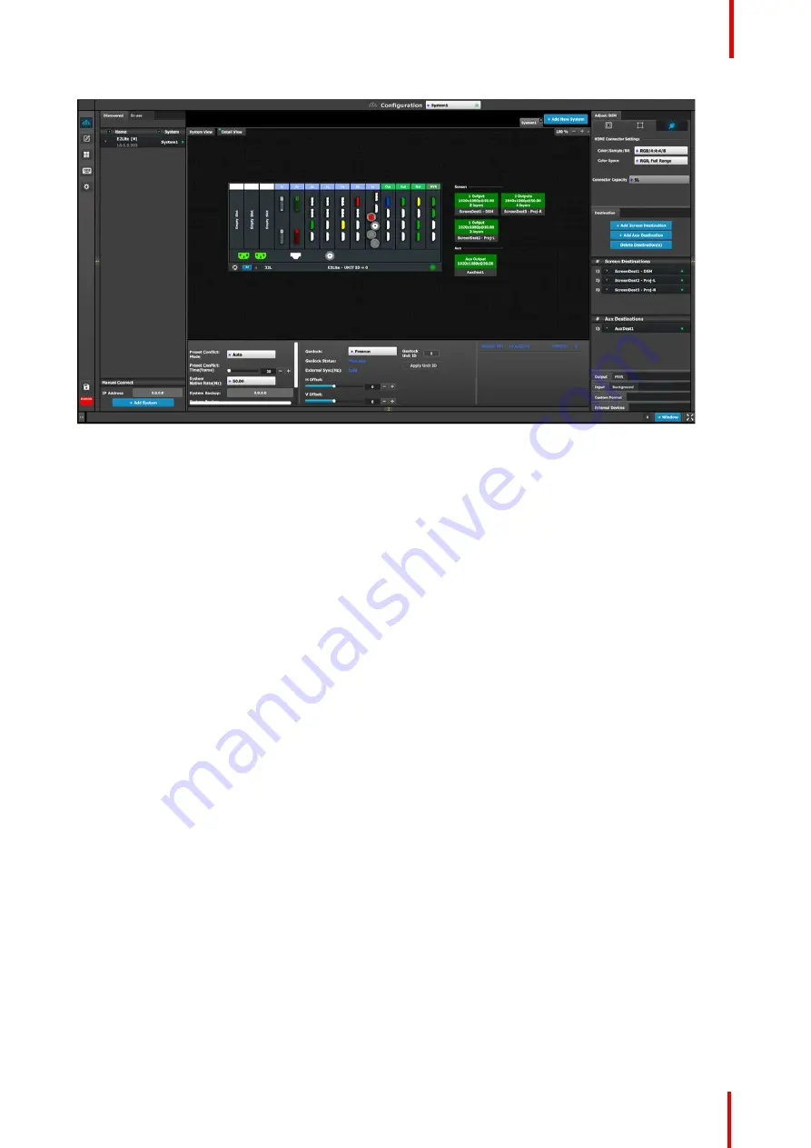
Image 6-9: System diagram area
In this area, the rear panel of the selected system is represented graphically with the cards, and the
connectors are color coded to indicate their status.
The color code is:
•
White = Connector available to add and configure.
•
Gray = Connector capacity set to NONE and is unavailable to add and configure.
•
Purple = Connector capacity set to SPLIT; connector 3 mirrors connector 1 (and connector 4 mirrors
connector 2), and connector is unavailable to add and configure.
Split-mode may be used with the DisplayPort connectors on the quad channel DisplayPort output card and
the SDI connectors on the tri-combo output card.
•
Red = Signal unavailable and connector configured into system.
•
Yellow = Signal available.
•
Green = Signal available and connector configured into system.
On the right hand side of the devices is a list of the created destinations (Screen and Auxiliary).
The tabs on the top allow access to the different systems connected to the EM GUI. The last tab allows the
users to create a new system.
A set of zoom buttons allows the user to reduce or enlarge the view size. This functionality is very useful when
the system is composed of more than one device.
How to create a new system
1.
Click on the
Add New System tab
on the top.
A new empty tab is created.
2.
Drop a device on this system. Refer to the procedure to add a device in the section
”
, page 72.
3.
Change the system name to avoid confusion when you control more than one system on the same Event
Master Toolset Software.
Double click on the tab, the tab background changes to a dark blue color indicating that modifications to the
name can be made.
How to remove system
1.
Click on the
“
X
”
button on the system tab.
Содержание Event Master E2 Lite
Страница 1: ...ENABLING BRIGHT OUTCOMES User s Guide E2 Lite and EC 40...
Страница 10: ...R5909934 00 E2 Lite and EC 40 10...
Страница 14: ...R5909934 00 E2 Lite and EC 40 14 Introduction...
Страница 18: ...R5909934 00 E2 Lite and EC 40 18 Safety...
Страница 32: ...R5909934 00 E2 Lite and EC 40 32 General...
Страница 46: ...R5909934 00 E2 Lite and EC 40 46 Hardware orientation...
Страница 168: ...R5909934 00 E2 Lite and EC 40 168 EM GUI orientation...
Страница 208: ...R5909934 00 E2 Lite and EC 40 208 Controller Orientation...
Страница 214: ...R5909934 00 E2 Lite and EC 40 214 Controller Configuration...
Страница 220: ...R5909934 00 E2 Lite and EC 40 220 Controller Operation...
Страница 226: ...R5909934 00 E2 Lite and EC 40 226 13 2 Process Overview Flow chart Image 13 2 E2 Lite Maintenance...
Страница 284: ...R5909934 00 E2 Lite and EC 40 284 E2 Lite Maintenance...
Страница 289: ...289 R5909934 00 E2 Lite and EC 40 Environmental Information 15...
Страница 300: ...R5909934 00 E2 Lite and EC 40 300 Specifications...
Страница 316: ...R5909934 00 E2 Lite and EC 40 316 Remote Control Protocol...
Страница 317: ...317 R5909934 00 E2 Lite and EC 40 Troubleshooting C...
Страница 320: ...R5909934 00 E2 Lite and EC 40 320 Troubleshooting...
Страница 329: ...R5909934 00 E2 Lite and EC 40 329 Index...


