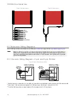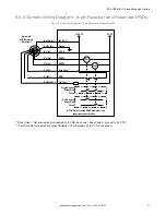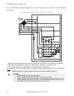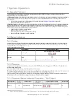
Figure 33. Individual cordsets
Vi
Gn/Ye
Bu
Bk
Wh
Or
Or/Bk
Bn
Scan Code Select
Ground
0V dc
OSSD1
OSSD2
EDM
Fault Output
+24V dc
Figure 34. Splitter cordsets
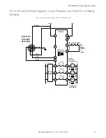
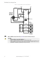
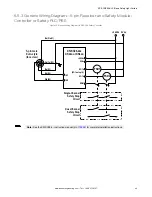
6.5 Reference Wiring Diagrams
Other interfacing modules and solutions are available, see
.
Note:
For interfacing modules or remotely located safety I/O blocks where pin 5 of a 5-pin M12 QD is not
earth ground, a 4-pin cordset where pin 5 is not physically present or is not electrically connected can be
used (such as MQDEC-406SS double-ended cordset). In such situations, earth ground must be provided
via the mounting brackets.
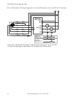
6.5.1 Generic Wiring Diagram—5-pin and 8-pin Emitter
Figure 35. Generic Wiring Diagram—Emitter
+24 VDC
n.c.*
n.c.*
0 VDC
Bn (Pin #1)
Gn/Ye (#5)
Bu (#3)
Bk (#4)
Wh (#2)
Emitter (5-pin Wiring)
5-pin male
M12/Euro-style
(face view)
+24 VDC 0 VDC
Bn (#1)
Gn/Ye (#7)
Bu (#6)
Bk (#5)
Wh (#4)
Vi (#8)
Or (#3)
Or/Bk (#2)
Emitter (8-pin Wiring)
n.c.*
n.c.*
ID In
Fault Out ***
8-pin male
M12/Euro-style
(face view)
Scan Code **
* All pins shown as no connection (n.c.) are either not connected or are paralleled to same color wire from the receiver cable.
** Scan Code 1: Not connected or connected to 0 V DC (as shown). Scan Code 2: connect to 24 V DC.
*** Fault Out: Not connected or connect indicator (70 mA maximum) to 0 V DC (as shown).
EZ-SCREEN
®
LS Basic Safety Light Curtain
46
www.bannerengineering.com - Tel: + 1 888 373 6767

