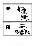
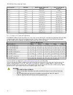

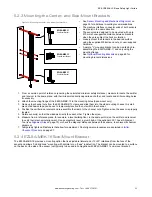

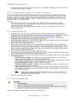

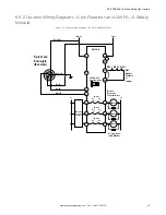
Figure 24. Side-Mount Bracket
EZLSA-MBK-16
Side Mount Bracket
•
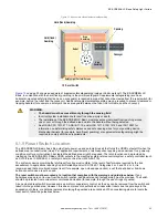
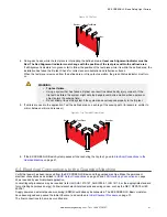
Mounting the Center- and Side-Mount Brackets
on page 33 for the general mounting procedure.
•
Sensor Mounting and Mechanical Alignment
on
page 34 for additional mounting recommendations.
•
The machine interface connector ends of both
sensors must point in the same direction.
•
The sensors are designed to be mounted with up to
910 mm of unsupported distance between brackets
when they are subject to shock or vibration.
•
on page 68 for
mounting bracket dimensions and the installation
guide.
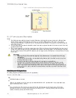
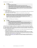
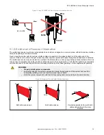
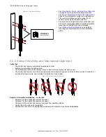
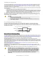
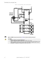
5.2.5 Sensor Mounting and Mechanical Alignment
Verify that:
•
The emitter and receiver are directly opposite each other
•
Nothing is interrupting the defined area
•
The defined area is the same distance from a common reference plane for each sensor
•
The emitter and receiver are in the same plane and are level/plumb and square to each other (vertical, horizontal, or
inclined at the same angle, and not tilted front-to-back or side-to-side)
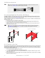
Figure 25. Incorrect Sensor Alignment
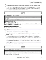
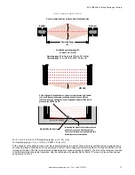
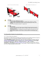
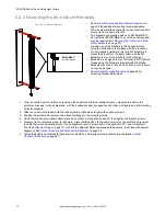
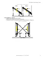
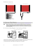
Angled or Horizontal Installations – verify that:
•
Distance X at the emitter and receiver are equal
•
Distance Y at the emitter and receiver are equal
•
Distance Z at the emitter and receiver are equal from parallel surfaces
•
Vertical face (the window) is level/plumb
•
Defined area is square. Check diagonal measurements if possible. See Vertical Installations.
EZ-SCREEN
®
LS Basic Safety Light Curtain
34
www.bannerengineering.com - Tel: + 1 888 373 6767


