
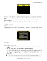
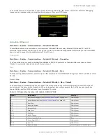
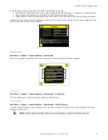


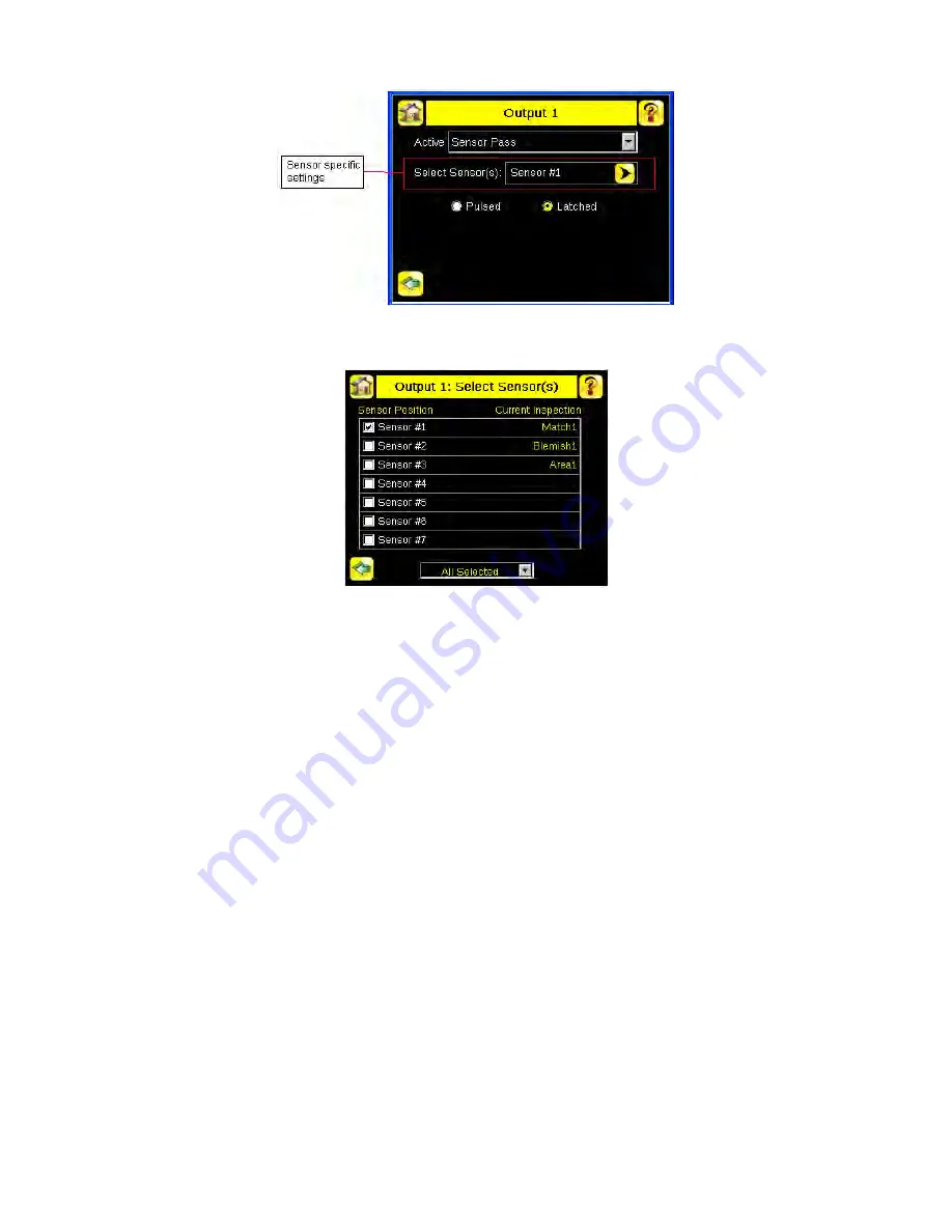
Click on the yellow arrow button to access the Select Sensor screen.
On the Select Sensor screen, the left column check box allows adding sensor position to be part of the logic that activates
the output. One or more sensor positions can be added. The right column on the table shows the sensor name(s) and their
respective position from the current inspection for reference.
The bottom drop list has two settings:
•
All Selected: All checked sensor positions must meet the setting criteria (Pass/Fail) to activate the output.
•
Any Selected: Any checked sensor position that meets the setting criteria (Pass/Fail) will activate the output.
When a selected sensor position is missing on the current inspection, the missing sensor(s) will not be part of the logic to
activate the output. For example: when only 2 sensors are included on the current inspection and the Output > Select
Sensor(s) has Sensor #1, Sensor #2 and Sensor #3 checked; only Sensor #1 and Sensor #2 will be used to determine the
output state, as Sensor #3 is not defined by the current inspection.
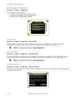
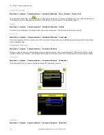
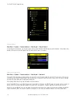
5.4.7 Display Settings
Main Menu > System > Display Settings
The Display Settings menu is for setting the Fail Hold Time, LCD Timeout, and doing a Touch Screen Calibration. Display
optimization can be enabled in the Advanced menu.
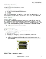
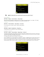
Fail Hold Time
Main Menu > System > Display Settings > Fail Hold Time
The Fail Hold Time determines how long a failed image is displayed on the LCD so that you can see what failed. The sensor
will continue to process any triggers and the inspection will continue normally. This time delay is just for the screen. You
can set this parameter from 0 to 3600 seconds using the slider at the bottom of the screen.
iVu Plus TG Gen2 Image Sensor
50
www.bannerengineering.com - Tel: 763.544.3164