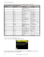
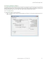


6. Click (only one time) on the Arrow button on the bottom left to return to the Industrial Ethernet window.
7. Click on Map to configure the PROFINET module map.
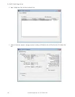
NOTE: The PROFINET module map displays S1 SS1 and S1 SS2 by default. S1 represents Slot 1,
SS1 represents SubSlot 1; S2 represents Slot 2, SS2 represents SubSlot 2. The other slots are not
configured by default.
The default PROFINET configuration consists of a single module plugged into Slot 1. This module, called the Device
Control and Status Module, accepts two submodules: the Inspection Result Submodule, plugged into Subslot 1, and the
Device Control Submodule, plugged into Subslot 2.
The Inspection Result Submodule provides the inspection results from the iVu Plus, including Pass Count, Fail Count,
and Current Inspection Time. See
Table 45
on page 149
NOTE: The Inspection Result Submodule does not provide any sensor-specific output data.
The Device Control Submodule allows the user to issue commands to the iVu Plus, such as Trigger, TEACH, and Product
Change. This submodule also provides the user with command feedback. See
Table 46
on page 150
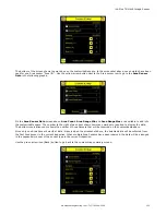
Adding sensor-specific output data requires the use of a sensor output submodule, plugged into Slot 2 Subslot 1. The
iVu Plus TG provides different options for configuring this submodule, based on the complexity of the inspection. The
selection of sensor output submodules is based on size, allowing the user to control network bandwidth use.
The Command Channel Module can be plugged into Slot 3. The selection of Command Channel Submodules is based on
the required length of the data output string. Link: Description of Submodules
Follow Step 8 and Step 9 to add a submodule to the configuration (optional).
iVu Plus TG Gen2 Image Sensor
www.bannerengineering.com - Tel: 763.544.3164
147