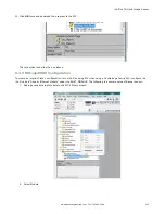


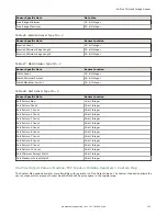
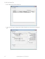


User may continue to add more data from any sensor type as required or reserve more sensors into the customizable
space.
Sensor Name and Sensor Type ID are global settings that are part of any individual sensor reservation. When they are
checked, they will be inserted into each sensor reservation.
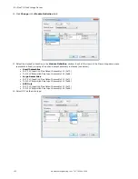
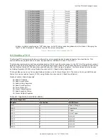
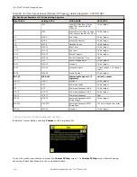
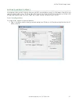
Here is an example of multiple sensors inspection and its output location on the customizable space.
There are only two Blemish sensors on the current inspection; Blemish3 location will be all zero on the customizable space.
The customizable space had not reserved a Match sensor, Match1 from the inspection will not be outputted on the
customizable space.
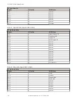
9.5.4 Flags
Writeable Input Bits are inputs to the iVu Plus (outputs from the PLC or HMI). They are used for basic control of the
sensor. They are accessible using function code 6 (Preset Single Register). The same control is also possible using Coils
00001-16, function code 05 (Force Single Coil).
Table 30: Input Bits: PLC Holding Register 1, also Coils 00001-16
Coil 16
Coil 15
Coil 14
Coil 13
Coil 12
Coil 11
Coil 10
Coil 9
Coil 8
Coil 7
Coil 6
Coil 5
Coil 4
Coil 3
Coil 2
Coil 1
Bit 15
Bit 14
Bit 13
Bit 12
Bit 11
Bit 10
Bit 9
Bit 8
Bit 7
Bit 6
Bit 5
Bit 4
Bit 3
Bit 2
Bit 1
Bit 0
Comma
nd
reserved reserved reserved reserved reserved reserved reserved reserved reserved reserved reserved Gated
Trigger
Trigger
Teach
Latch
Product
Change
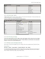
Read-only Input ACK Bits are outputs from the iVu Plus sensor (inputs to the PLC or HMI). They are used to acknowledge
each of the input bits sent from the PLC. For example, if the PLC changes the Trigger bit (from Input Bits, above) from a 0
to a 1, the iVu will change the Trigger ACK bit from a 0 to a 1 in response. This information is available as Input Registers
or Holding Registers. Use either function code 04 (Read Input Registers) or function code 03 (Read Holding Registers). The
same data can be seen as Inputs (10000) using Modbus function code 02 (Read Input Status).
Table 31: Input ACK Bits: PLC Input Register 1 or Holding Register 1001, also Inputs 10001-16
Input 16 Input 15
Input 14
Input 13
Input 12
Input 11
Input 10
Input 9
Input 8
Input 7
Input 6
Input 5
Input 4
Input 3
Input 2
Input 1
Bit 15
Bit 14
Bit 13
Bit 12
Bit 11
Bit 10
Bit 9
Bit 8
Bit 7
Bit 6
Bit 5
Bit 4
Bit 3
Bit 2
Bit 1
Bit 0
Comma
nd ACK
reserved reserved reserved reserved reserved reserved bit
8reserv
ed
reserved reserved reserved reserved Gated
Trigger
ACK
Trigger
ACK
Teach
Latch
ACK
Product
Change
ACK
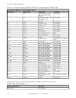
Read-only Status Bits are outputs from the iVu Plus sensor (inputs to the PLC or HMI). They are used to report the basic
status of the sensor and the last inspection run. This information is available as Input Registers or Holding Registers. Use
either function code 04 (Read Input Registers) or function code 03 (Read Holding Registers). The same data can be seen
as Inputs (10000) using Modbus function code 02 (Read Input Status).
Table 32: Status Bits: PLC Input Register 2 or Holding Register 1002, also Inputs 10017-32
Input 32 Input 31
Input 30
Input 29
Input 28
Input 27
Input 26
Input 25
Input 24
Input 23
Input 22
Input 21
Input 20
Input 19
Input 18
Input 17
Bit 15
Bit 14
Bit 13
Bit 12
Bit 11
Bit 10
Bit 9
Bit 8
Bit 7
Bit 6
Bit 5
Bit 4
Bit 3
Bit 2
Bit 1
Bit 0
Executio
n Error
System
Error
Teach
Error
Missed
Trigger
reserved reserved reserved reserved Output
3
Output
2
Output
1
reserved Ready
Latch
Read/No
Read
Pass/
Fail
Ready
iVu Plus TG Gen2 Image Sensor
136
www.bannerengineering.com - Tel: 763.544.3164