
FailureCode
The Failure Code is set when an error occurs with the reader. The following is a table of Failure Codes:
Failure Code
Name
0×01
Input Failure
0×02
Communications Failure
0×04
Reader Failure
0×08
Software Error
0×10
Remote Failure
LastItemSeqNumber
The Last Item Sequence Number is written with the Item Sequence Number by the Originator (PLC) to acknowledge the
receipt of the Item Data. If fragmentation is used, this value is not written until the complete message is received.
LastItemDataSize
The Last Item Data Size is the total size of the Item Data that is currently contained as a valid message in the LastItemData
array. This data is updated at the exact same time as when the LastItemSeqNumber increments, when a new item has been
completely received, even if it took multiple packets to transfer in 128 byte fragments.
LastItemData
LastItemData is the 4096 byte array that contains the last full message transferred by the ABR to the PLC. This array is
updated at the same time as LastItemDataSize and LastItemSeqNumber, after all fragments of the message have been re-
assembled in the AOI. It might not always be the latest result message generated by the ABR if the PLC has fallen behind
and the ABR is buffering multiple results waiting to finish sending them to the PLC. Only the bytes that fall within the size of
the LastItemDataSize are overwritten, so there could also be old data left in the upper array addresses when a shorter
message arrives than the previous message.
8.3 Modbus/TCP
The Modbus/TCP protocol provides device information using register and coil banks defined by the ABR.
This section defines the register and coil banks. By specification, Modbus/TCP uses TCP port 502. The ABR functions as a
Modbus/TCP Client, so the host controller (usually a PLC) must act as a Server.
The following registers are used to send values back and forth from the barcode reader to the PLC. ABR series reader read-
only output data messages are written to Holding Registers (40000) using Modbus function code 16 (Preset Multiple
Registers). The ABR Input Bits are read every 50 milliseconds from the PLC as Inputs (10000) using Modbus function code
02 (Read Input Status). The state of the ABR Output Bits are written to the PLC on Coils (00000) using Modbus function
code 05 (Write Single Coil).
Modbus Function Codes Used
02: Read Input Status
05: Force Single Coil
16: Preset Multiple Registers
Table 4: ABR Input Bits (10001–10008)
02: Read Input Status
Register
ABR
Input Bit Position
10001
Input Bit 0
10002
Input Bit 1
10003
Input Bit 2
10004
Input Bit 3
10005
Input Bit 4
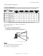
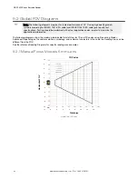
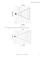
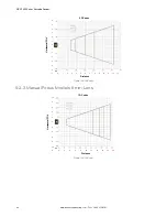
ABR 7000 Series Barcode Reader
78
www.bannerengineering.com - Tel: + 1 888 373 6767


