Micron Communications MicroBadge 4053, User Manual
The Micron Communications MicroBadge 4053 is an innovative communication device designed for seamless connectivity. Enhance your user experience with the comprehensive User Manual, available for free download from our website. Explore its advanced features and functionalities while ensuring efficient operation effortlessly.
Share
Download


Reviews:
No comments
Related manuals for MicroBadge 4053
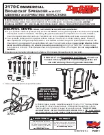
2170
Brand: EarthWay Pages: 8

M40
Brand: EarthWay Pages: 6

SmartTerminal ST-1044
Brand: Cherry Pages: 4

BV7342T
Brand: Boss Audio Systemsu Pages: 33

SD 236BT/RDS/USB/AX
Brand: Majestic Pages: 6

tDynamo
Brand: Magtek Pages: 2

OXYGEN VX1
Brand: 3Dlabs Pages: 44

Icy Box IB-PCI1901-C32
Brand: RaidSonic Pages: 16

6S.5T03
Brand: Williams Pages: 8

XDMA6540
Brand: Dual Pages: 38

CDC-X427
Brand: Aiwa Pages: 9

CR-505DAB
Brand: Onkyo Pages: 40

VME9020TS
Brand: Audiovox Pages: 78

HT-TEMPLE-1
Brand: hillvert Pages: 5

XRT86VL38
Brand: Exar Pages: 442

Moby/8500
Brand: Ingenico Pages: 10

3.4 RCD 510
Brand: Volkswagen Pages: 38

KDC-4047U
Brand: Kenwood Pages: 24


