52 / 119
0006081062_200709
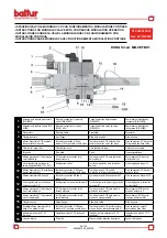
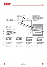
BGN 540 LX / LX-V ELECTRODES ADJUSTMENT DIAGRAM
N° 0002933850
Rev. 12/06/2002
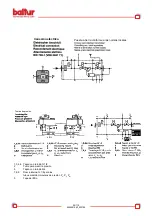
CONTROL BOX FOR LFL 1... SERIES 02 GAS BURNERS
Control box for burners of ave-
rage and high power, with forced
draught, intermittent service
(*), 1 or 2 stages, or modulating
types, with supervision of the
air pressure for controlling the
air damper.
This control box bears the EC
mark, in accordance with the Gas
and Electromagnetic Compatibi-
lity Directive.
* For reasons of safety, it is neces
-
sary to make at least one control
-
led stop every 24 hours!
As regards the standards
The following LFL1… features
exceed the standards, offering a
high level of additional safety:
- The flame detector test and false
flame test start immediately after
the tolerated post-combustion
time. If the valves remain open,
or do not close completely after
adjustment stops, a lock-out stop
is triggered at the end of the to-
lerated post-combustion period.
The tests will end only at the end
of the pre-ventilation time of the
next start-up.
- The validity of working of the
flame control circuit is checked
each time the burner starts up.
- The fuel valve control contacts
are checked for wear during the
post-ventilation time.
- A built-in fuse in the appliance
protects the control contacts from
any overloads that may occur.
As regards the burner control
- The equipment allows operation
with or without post-ventilation.
- Controlled activation of the air
damper to ensure pre-ventilation
with nominal airflows. Positions
checked: CLOSED or MIN (posi
-
tion of ignition flame on start-up);
OPEN at the beginning and MIN
at the end of the pre-ventilation
time. If the servomotor does not
position the air damper at the
points described, the burner does
not start-up.
- Ionization current minimum value
= 6mA
- UV cell current minimum value =
70mA
- Phase and neutral must not be
inverted.
- Any place may be used for in
-
stallation and assembly (IP40
protection).
Содержание BGN 200 LX
Страница 27: ...54 119 0006081062_200709 Notes on the programmer Programmer sequence Output signals on terminal...
Страница 35: ...98 119 0006081062_200709...
Страница 36: ...99 119 0006081062_200709...
Страница 44: ...107 119 0006081062_200709 SCHEMA ELETTRICO WIRING DIAGRAM ELECTRIC DIAGRAM...
Страница 45: ...108 119 0006081062_200709 SCHEMA ELETTRICO WIRING DIAGRAM ELECTRIC DIAGRAM...
Страница 46: ...109 119 0006081062_200709 SCHEMA ELETTRICO WIRING DIAGRAM ELECTRIC DIAGRAM...
Страница 47: ...110 119 0006081062_200709 SCHEMA ELETTRICO WIRING DIAGRAM ELECTRIC DIAGRAM...
Страница 48: ...111 119 0006081062_200709 SCHEMA ELETTRICO WIRING DIAGRAM ELECTRIC DIAGRAM...
Страница 49: ...112 119 0006081062_200709 SCHEMA ELETTRICO WIRING DIAGRAM ELECTRIC DIAGRAM...
Страница 50: ...113 119 0006081062_200709 SCHEMA ELETTRICO WIRING DIAGRAM ELECTRIC DIAGRAM...
Страница 51: ...114 119 0006081062_200709 SCHEMA ELETTRICO WIRING DIAGRAM ELECTRIC DIAGRAM...
Страница 52: ...115 119 0006081062_200709 SCHEMA ELETTRICO WIRING DIAGRAM ELECTRIC DIAGRAM...
Страница 53: ...116 119 0006081062_200709 SCHEMA ELETTRICO WIRING DIAGRAM ELECTRIC DIAGRAM...
Страница 54: ...117 119 0006081062_200709 SCHEMA ELETTRICO WIRING DIAGRAM ELECTRIC DIAGRAM...
Страница 55: ...118 119 0006081062_200709 SCHEMA ELETTRICO WIRING DIAGRAM ELECTRIC DIAGRAM...
Страница 56: ...119 119 0006081062_200709 SCHEMA ELETTRICO WIRING DIAGRAM ELECTRIC DIAGRAM...

