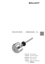
background image

1

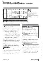
Intended use

The BTL magnetostrictive linear position sensor, together 

with a machine controller (e.g. PLC), comprises a position 

measuring system. It is intended to be installed into a 

machine or system and used in the industrial sector. 

Flawless function in accordance with the specifications in 

the technical data is ensured only when using original 

Balluff accessories. Use of any other components will void 

the warranty.

Opening the BTL or non-approved use are not permitted 

and will result in the loss of warranty and liability claims 

against the manufacturer.

General safety notes

Installation

 and 

startup

 may only be performed by 

trained specialists.

The 

operator

 is responsible for ensuring that local safety 

regulations are observed. In particular, the operator must 

take steps to ensure that a defect in the BTL will not result 

in hazards to persons or equipment.

If defects and unresolvable faults occur in the BTL, take it 

out of service and secure against unauthorized use.

Downloading further instructions

A complete user's guide can be downloaded from the 

Internet at 

www.balluff.com

 or requested via e-mail from 

[email protected]

.

Dimensions and function

The BTL contains the waveguide which is protected by an 

outer stainless steel tube (rod). A magnet is moved along 

the waveguide. This magnet is connected to the system 

part whose position is to be determined.
The magnet defines the position to be measured on the 

waveguide.

Installation

NOTICE!

Interference in function

Improper installation can compromise the function of the 

BTL and result in increased wear.


The mounting surface of the BTL must make full 

contact with the supporting surface.


The bore must be perfectly sealed (O-ring/flat seal).

Screw the BTL with mounting thread into the mounting 

hole (max. torque 100 Nm).

Radial cable outlet

During installation, the direction of the cable 

outlet is determined by the thread.

For horizontal assembly with nominal lengths > 500 mm, 

support the rod and tighten it at the end if necessary (only 

possible with a diameter of 10.2 mm).

If installed in a hydraulic cylinder, the magnet should not 

make contact with the rod. Minimum bore diameter in the 

support piston:

Rod diameter

Bore diameter

10.2 mm

At least 13 mm

8 mm

At least 11 mm

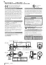
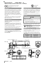
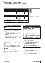
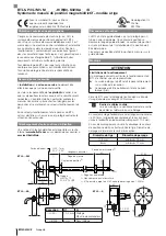
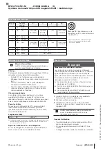
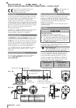
BTL5-P/I/L/M1-M _ _ _ _ -H/W(8) -S32/KA _ _ /K _ _

Magnetostrictive Linear Position Sensor – Rod Style

english

The CE Mark verifies that our products

meet the requirements of the current

EMC Directive.

UL approval

File No.

E227256

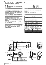
Ø 65

21

35

~42

0.5 Ø 25

~20

~20

10

43

25

~12

60

Ø 

D1

G

10

0.5 Ø 25

Thread

H: M18×1.5

W: 3/4"-16UNF

H: 40 -1mm

W: 2" -0.04"

Mounting surface

Damping zone1)

BTL5…-KA _ _

BTL5…-K_ _

BTL5…-S32

Magnet 2)

1)

1)

Unusable area

2)

Not included in scope of delivery

3)

Ø 5 for hook spanner Ø 65, max. tightening torque 100 Nm

Nominal length =
Measuring range

Version

D1

G

…-H/W-…

10,2 mm

Thread


M4x4/6 deep

…-H8/W8-…

8 mm

No thread

3)

Содержание BTL5-P/I/L/M1-M-H/W(8)-S32/KA/K Series

Страница 1: ...deutsch Kurzanleitung english Condensed guide fran ais Notice r sum e italiano Istruzioni brevi espa ol Instrucciones breves BTL5 P I L M1 M_ _ _ _ H W 8 S32 KA_ _ K_ _...

Страница 2: ...ser Positionsgeber ist mit dem Anlagen bauteil verbunden dessen Position bestimmt werden soll Der Positionsgeber definiert die zu messende Position auf dem Wellenleiter Einbau ACHTUNG Funktionsbeeintr...

Страница 3: ...lecht aus Kupfer Einzeldr h ten Bedeckung mindestens 85 Steckerausf hrung Schirm im Steckverbinder mit dem Steckergeh use fl chig verbinden Kabelausf hrung BTL seitig ist der Kabelschirm mit dem Geh u...

Страница 4: ...o the system part whose position is to be determined The magnet defines the position to be measured on the waveguide Installation NOTICE Interference in function Improper installation can compromise t...

Страница 5: ...Connector version Shield is internally connected to connector housing Cable version On the BTL side the cable shielding is connected to the housing Ground the cable shielding on the controller side co...

Страница 6: ...du guide d ondes Le capteur de position est reli l l ment de l installation dont la position doit tre d termin e Le capteur de position d finit la position mesurer sur le guide d ondes Montage ATTENT...

Страница 7: ...avec un c ble blind Blindage tresse de fils de cuivre couverture minimum 85 Version connecteur relier plat le blindage du connecteur au bo tier de connecteur Version c ble c t BTL le blindage de c bl...

Страница 8: ...quale deve essere determinata la posizione Il datore di posizione definisce la posizione da misurare sulla guida d onda Montaggio ATTENZIONE Anomalie funzionali Il montaggio non corretto pu ostacolare...

Страница 9: ...mato Schermatura maglia di singoli fili di rame copertura minima 85 Versione con connettore collegare la schermatura nel connettore con il corpo del connettore sull intera superficie Versione con cavo...

Страница 10: ...unido con el componente de la instalaci n cuya posici n se desea determinar El sensor de posici n define la posici n que se ha de medir en el gu aondas Montaje ATENCI N Merma del funcionamiento Un mon...

Страница 11: ...alla de hilos individuales de cobre cobertura m nima del 85 Ejecuci n de conector conecte superficialmente el blindaje en el conector con la carcasa del mismo Ejecuci n de cable en el lado del BTL el...

Страница 12: ...500 mm 10 2 mm 10 2 mm 13 mm 8 mm 11 mm BTL5 P I L M1 M_ _ _ _ H W 8 S32 KA_ _ K_ _ CE EMV UL E227256 65 21 35 42 0 5 25 20 20 10 43 25 12 60 D1 G 10 0 5 25 H M18 1 5 W 3 4 16UNF H 40 1mm W 2 0 04 1 B...

Страница 13: ...85 BTL BTL BTL BTL5 500 m4 4 0 6 mm2 AWG19 BTL5 P I L M1 M_ _ _ _ H W 8 S32 KA_ _ K_ _ P I L M 1 YE Init 2 GY Start Stop 2 Start Stop 2 Tor Start Stop 1 S32 BTL 8 M16 3 PK Init 4 RD 3 3 GND 5 GN Start...

Страница 14: ......

Страница 15: ......

Страница 16: ...uhausen a d F Phone 49 7158 173 370 Fax 49 7158 173 691 service balluff de US Service Center USA Balluff Inc 8125 Holton Drive Florence KY 41042 Phone 859 727 2200 Toll free 1 800 543 8390 Fax 859 727...

Отзывы: