

Page 5
EL1500 - 40916_01_C
TORQUE
RANGE
FOR TB1:
27-30 IN. LBS.
H
OT
BLA
C
K
NEUTRAL
W
HITE
H
O
T
R
ED
K6
K13
K4
K2
K3
W
HT A
C
BLK AC
J61
J62
J11
J66 J6
5
J1
5
J16
J2
5
J63 J64
C
LA
SS
G
F
USE 30
A
F
5
TB1
HTR2
HTR1
J101
F2
J100
B
al
boa
SWITCHBANK A
S1
J6
J7
J8
J13
J44
J60
J22
E.GN
D
1 SP. EXT. RLY
TST
CFG
AUX. F
SEN. A
SEN. B
W10
VAC
RED AC
J32 J33 J34
J36
J37
J3
5
T1
FUSE .3A 2
5
0V
F4
E
L1
5
00
P
/N 2207
5
_B
CO
PYRIGHT 2008
G
C
K1
J1
J2
J23
J74
J48
J46
W1
J
5
0
J17
G
C
W4
G
C
W7
2-SP
EXT RLY
FUSE 20A 2
5
0V
K8
K9
F8
G
C
G
C
J2
0
J4
5
J29
J47
W2
J69
J70
W3
FUSE 3A 2
5
0
V
F1
G
C
U4
K
5
J71
ADCM
MAIN
PANEL
MAIN ML PNL
R
EM
O
T
E
J8
2
J12
J3
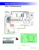
For 120V Systems,
DIP A2 and A3 must be OFF
and Jumper Wire added.
5
.
5
kW
Heater rated @ 240V
(Approx. 1.4kW @ 120V)
Audio VisualAudio Visual
Do not remove Fuse F8 (20A)
12V
Light
G
R
B
W
J1
W1
J7
J6
F30A 480V
X-P332
PN
55
137
P/N 22909 REV B
Not Used
Ozone
C
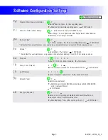
onfiguration
Settings
Enabled
2-Spd P1
Real-Time
C
lock Board
NOT Installed
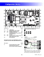
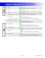
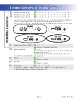
Wiring Configuration and DIP Settings
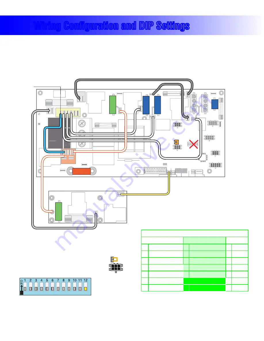
Setup 1 (As Manufactured)
s 60UMP3PEED
s 60UMP3PEED
s 6"LOWER3PEED
s 6#IRC0UMP
s 63PA,IGHT
s 6/ZONE
s 6!<6
(Stereo)
s 6K7(EATER
s -,-AIN0ANEL
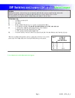
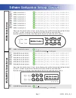
Switchbank A
A4, Filters by Time
A6,
A5,
A8,
A9, Filter Duration 2 hr.
A7,
A11, Special Amp Rule OFF
A12, Memory ON
A10, No Edit
When the Logic Jumper is installed on J82 (CFG),
Software Config. Settings are enabled.
DIP Switches will operate as shown.
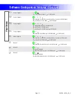
}
See Table 2
Circ Behavior
Pumps w/Heat
See Table 1
}
See Table 3
Pump 2
}
CFG
J2
J82
100
114
35
SSID #
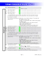
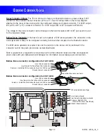
120 Volt Connections
240 Volt Connections
Black AC Jumpers
12 Volt Connections
Relay Control Wires
Wiring Color Key
Typically Line voltage
Typically Line voltage for 2-speed pumps
Neutral (Common)
Ground
Note flat sides in connector
1
2
3
4
Board Connector Key
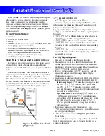
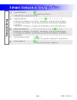
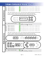
WARNING:
Main Power to system should be turned OFF BEFORE adjusting DIP switches.
WARNING:
Persistent Memory (A12) must be RESET to allow new DIP switch settings to take effect. (See Persistent Memory page)
Indicate DIP positions needed for this system.
Special Connections/Notes:________________
________________________________________
________________________________________
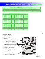
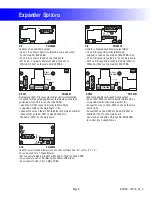
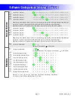
Expander Boards
(Select configuration)
Device
Ex Board Model
Voltage
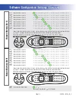
Blower (2/3-Spd)
X-B
120V
Pump 3 - 1 Spd
X-TB
240V
Pump 4 - 1 Spd
X-P
Mister
X-P231
ADCM Splitter
X-P332
Cables\Adapters
PS-34
H
Ozone on J17
H
Ozone on J29
H
Include Real-Time Clock capability


