
Page 4
EL1500 - 40916_01_C
Persistent Memory and Powering Up
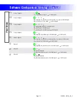
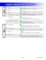
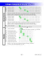
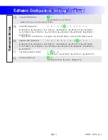
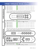
!NYTIMEYOUCHANGE$)03WITCHESOR3OFTWARE#ONFIGURATION3ETTINGSTHAT
affect parameters the user can change (any filter settings, set temperature
default, Celsius vs Fahrenheit, 12-hour vs 24-hour time, reminders
SUPPRESSIONETC YOUMUSTRESET0ERSISTENT-EMORYFORYOUR$)03WITCH
or Software Configuration Settings changes to take effect. You should also
reset Persistent Memory after loading a new file into a board (using the ESM,
purchased seperately).
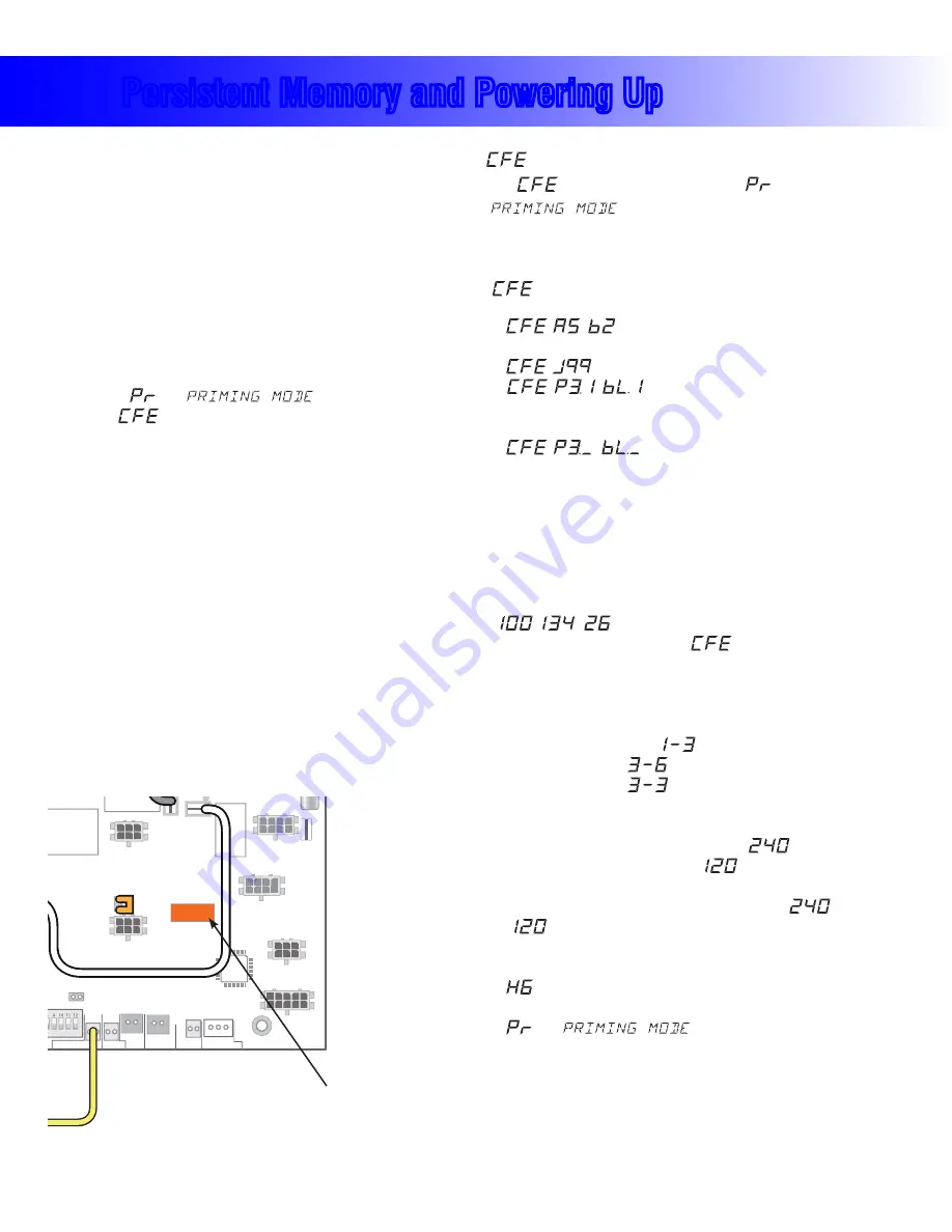
To reset Persistent Memory:
s0OWERDOWN
s3ET!/.3EEILLUSTRATIONBELOW
s0OWERUP
s7AITUNTILh
vORh
” is displayed on your panel.
.OTE)Fh
” appears see section below.
s3ET!/&&4HISCANBEDONESAFELYWITHPOWERONIFYOUUSEA
nonconductive tool such as a pencil to push the switch back to the OFF
position. Otherwise, power down before setting A12 OFF)
s0OWERUPAGAINIFYOUPOWEREDDOWNINTHEPREVIOUSSTEP
s&ORALLOTHERPOWERUPSLEAVE!/&&
About Persistent Memory and Time of Day Retention:
This system uses memory that doesn’t require a battery to store a variety
OFSETTINGS7HATWEREFERTOAS0ERSISTENT-EMORYSTORESALLTHE5SER
Preferences, as well as all the filter settings, the set temperature, and the heat
mode.
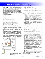
Persistent Memory is not used for Time of Day. Time of Day needs to be
hKEPTRUNNINGvNOTJUSTSTORED WHILETHEPOWERISOFFSOANOPTIONAL2EAL
Time-Clock (RTC) board keeps track of Time-of-Day while the unit is off.
Time-of-day retention, and time-of-day retention alone, is controlled by the
RTC Board. This board should be installed on any system that uses a control
panel that displays time-of-day. The RTC Board must be removed from any
system that does not have a panel installed that supports time-of-day.
message on power up:
)Fh
vAPPEARSBEFOREANDINSTEADOF h
” or
h
vYOUHAVENOTCONFIGURED$)03WITCHESANDOR
Software Configuration Settings in a valid manner. This must be corrected
before you can reset Persistent Memory.
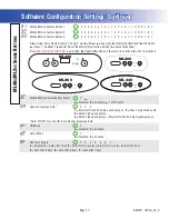
4HESWITCHNUMBERSJUMPERSORCONFIGURATIONSETTINGSDISPLAYEDAFTER
h
” are ones with which the system has found a configuration problem.
For example:
s h
” would mean that the combination of how you’ve
set A5 and how you’ve set B2 is not supported on this system.
s h
vWOULDMEANTHATTHEREISAPROBLEMWITHJUMPER*
sh
” would mean that the combination of how
you’ve set pump 3 for 1-speed and blower for 1-speed is not supported on
this system.
s h
” would mean that the combination of how
YOUVESET$)0SWITCHESWHICHHAVEBEENASSIGNEDTOPUMPANDBLOWERIS
not supported on this system.
Power Up Display Sequence
5PONPOWERUPYOUSHOULDSEETHEFOLLOWINGONTHEDISPLAY
s 4HREENUMBERSINAROWWHICHARETHE33)$THE3YSTEM3OFTWARE)$
The third display of these numbers is the Software Version, which should
match the version of your system. For example, if these three numbers are
, that is a Mach 3 EL8000 at version 26.
s )FTHEREISA#ONFIGURATION%RRORTHE
message (see above) will
appear at this point (and none of the messages below will display).
Otherwise what comes next is:
s !NINDICATIONOFEITHERTHEINPUTVOLTAGEDETECTED%, OR
THEHEATERWATTAGERANGESUPPORTED%,',',',
Heater wattage display:
h
” means the system supports a heater
FROMK7TOK7h
” means the system supports a heater
FROMK7TOK7h
vMEANSTHESYSTEMSUPPORTSAK7
heater only. (These ranges may be modified slightly in the case of special
heaters, which the next bullet covers.)
Input voltage display:
!SYSTEMSHOWINGh
vSUPPORTSK7
TOK7HEATERS!SYSTEMSHOWINGh
” supports the very same
heaters, although at 120V those heaters will function at only 1/4 of their
6RATEDWATTAGE4HESYSTEMSHOWSONLYEITHERh
vORh
” as a general indication of input voltage; it does not show the
actual input voltage.)
s )FYOURSYSTEMISUSINGASPECIALTYPEOFHEATERADISPLAYSUCHAS
h
vMAYAPPEARNEXT)FYOURSYSTEMISUSINGTHEGENERIC"ALBOAHEATER
no heater type display will appear.
s h
vORh
” will appear to signal the start of
Priming Mode.
!TTHISPOINTTHEPOWERUPSEQUENCEISCOMPLETE2EFERTOTHE5SER'UIDE
for the ML Series panel on your system for information about how the spa
operates from this point on.
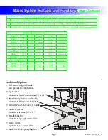
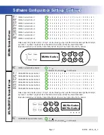
J6
J7
J8
J13
J44
J60
J22
1 SP. EXT. RLY
TST
CFG
AUX. F
SEN. A
SEN. B
VAC
J1
J2
7
2-SP
EXT RLY
K9
J2
0
J4
5
W2
J69
J70
U4
K
5
J71
ADCM
MAIN
PANEL
MAIN ML PNL
R
EM
O
T
E
J8
2
J3
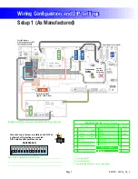
C
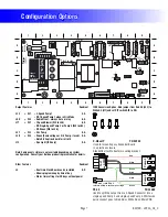
onfiguration
Settings
Enabled
RT
C
Real-Time
C
lock Board
Optional Real-Time-Clock board
plugs into J3.


