Page 17
EL1500 - 40916_01_C
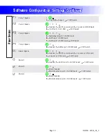
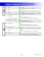
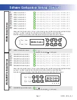
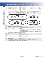
ML90x Custom Button 1
1
2 3 4 5 6 b g F E o t d P n A U r O H 9 L 8 7
ML90x Custom Button 2
1
2 3 4 5 6 b g F E o t d P n A U r O H 9 L 8 7
ML90x Custom Button 3
1
2 3 4 5 6 b g F E o t d P n A U r O H 9 L 8 7
ML90x Custom Button 4
1
2 3 4 5 6 b g F E o t d P n A U r O H 9 L 8 7
ML90x Custom Button 5
1
2 3 4 5 6 b g F E o t d P n A U r O H 9 L 8 7
ML90x Custom Button 6
1
2 3 4 5 6 b g F E o t d P n A U r O H 9 L 8 7
ML90x Custom Button 7
1
2 3 4 5 6 b g F E o t d P n A U r O H 9 L 8 7
ML90x Custom Button 8
1
2 3 4 5 6 b g F E o t d P n A U r O H 9 L 8 7
1-6 =
Assigns Pump Number (Pump 1, Pump 2, etc);
b =
Blower;
g =
Spa Light;
F =
Fiber-Optic wheel/light;
E =
EitherLight;
o =
Option 1;
t =
Mister 1;
d =
Mister 2/Cool;
P =
Mister 3/Elec Heat;
n =
Ext Heat;
A =
Sound Mode Select;
U =
Button Disabled;
r =
Air Valve;
O =
Option 2;
H =
Option 3;
9 =
Invert;
L =
Option 4;
8 =
Stir;
7 =
Option 5
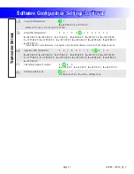
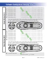
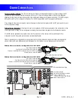
ML90x Series
1
2
3
4
8
7
6
5
Time
Warm
Warm
Mode
e
Cool
ML90x Custom Buttons Enable
n
Y
n
=
Disabled;
Y
=
Enabled;
= 1 DIP Switch
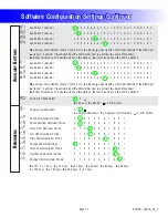
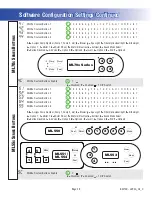
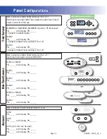
ML75x/MX75x Custom Button 1
1
2 3 4 5 6 b g F E o t d P n A U r O H 9 L 8 7
ML75x/MX75x Custom Button 2
1
2 3 4 5 6 b g F E o t d P n A U r O H 9 L 8 7
ML75x/MX75x Custom Button 3
1
2 3 4 5 6 b g F E o t d P n A U r O H 9 L 8 7
ML75x/MX75x Custom Button 4
1
2 3 4 5 6 b g F E o t d P n A U r O H 9 L 8 7
ML75x/MX75x Custom Button 5
1
2 3 4 5 6 b g F E o t d P n A U r O H 9 L 8 7
ML75x/MX75x Custom Button 6
1
2 3 4 5 6 b g F E o t d P n A U r O H 9 L 8 7
1-6 =
Assigns Pump Number (Pump 1, Pump 2, etc);
b =
Blower;
g =
Spa Light;
F =
Fiber-Optic wheel/light;
E =
EitherLight;
o =
Option 1;
t =
Mister 1;
d =
Mister 2/Cool;
P =
Mister 3/Elec Heat;
n =
Ext Heat;
A =
Sound Mode Select;
U =
Button Disabled;
r =
Air Valve;
O =
Option 2;
H =
Option 3;
9 =
Invert;
L =
Option 4;
8 =
Stir;
7 =
Option 5
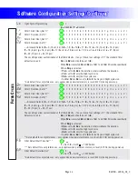
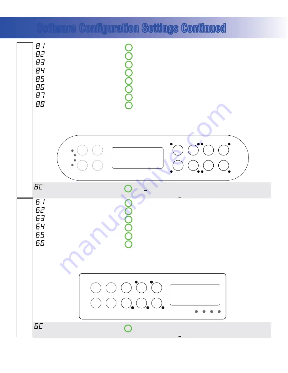
ML75x Series
MX75x Series
6
5
4
1
2
3
Time
Warm
m
m
W
W
Mode
e
e
Cool
ML750/MX750 Custom Buttons Enable
n
Y
n
=
Disabled;
Y
=
Enabled;
= 1 DIP Switch
Software Configuration Settings Continued
ML75
X
/MX75
X
S
ERIES
B
UTTONS
ML90
X
S
ERIES
B
UTTONS


