Page 20
EL1500 - 40916_01_C
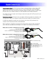
Ozone Connections
W10
J48
J46
J50
J17
G
C
W4
G
C
W7
FUSE 20A 250V
K8
K9
F8
G
C
G
C
J29
J12
J47
W2
J70
W3
FUSE 3A 250V
F1
G
C
K5
J71
MAIN
PANEL
MAIN ML PNL
CFG
J1
J45
J82
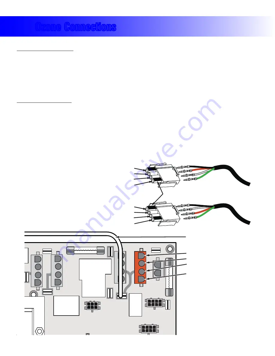
Use this slot for the leftover Red conductor
Line - Black conductor
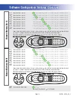
Balboa Ozone connector configuration for 120V 60Hz
Ground (Green) conductor
Flat sides of sockets as shown
Common - Install the White conductor here for 120V ozone
Use this slot for the leftover White conductor
Line - Black conductor
Balboa Ozone connector configuration for 240V 60Hz
Ground (Green) conductor
Common - Install the Red conductor here for 240V ozone
B
G
B
G
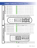
Use this slot for the leftover conductor
Line - Black conductor
Ground (Green) conductor
Common - Red for 240V or
White for 120V ozone (See W2 wire)
W2 wire determines voltage
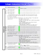
Ozone Connector Voltage:
The EL circuit board is factory configured to deliver a preset voltage (120V
or 240V) to the on-board ozone connector (J29 or J17). See the ratings table on the wiring diagram
attached to the cover of the enclosure for the configured voltage and output connector. For 240V output,
W2 (J29) or W7 (J17) connects to Red AC. For 120V output, W2 or W7 connects to White AC.
The voltage to the ozone connector can be changed in the field if required. W2 or W7 just need to be set
for the required voltage.
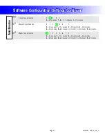
Balboa Ozone Generator:
If the board is set up to operate a 120V ozone generator, the connector on the
ozone generator is likely to be configured correctly, but should be compared to the illustration below.
If a 240V ozone generator is required, be sure the red wire in the ozone cord is positioned in the
connector next to the green ground wire as described below.
Note: A special tool is required to remove the pins from the connector body once they are snapped in
place. Check with your Balboa Account Manager for information on purchasing a pin-removal tool.


