


BA-440 DualBeam Barcode Reader Quickstart Guide Ver 5
13. Test Wiegand output with Verifier, continued
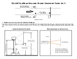
The Green, Red, and Yellow LED indicators are mounted on the rear of the circuit board. Look
behind
the left side
of the Verifier for the LED indicators as shown here.
The LED's are located in this position in an attempt to keep them out of direct sunlight. You may still need to shade
them with your hand if the Sun shines directly on them.
To use the Wiegand verifier function with the module mounted on a BA-440, turn the "test" switch ON,
which is down toward the arrow. The Green, Red, and Yellow LED's on the left side of the board will
blink
once
in sequence to show that the verifier is ready. Remember that the LED's are
behind
the
circuit board as shown, you should stand behind the reader to see them clearly.
NOTE:
To preserve battery life, the verifier circuit will run for 10 minutes after the switch is ON, then it will go into
power saving mode (hibernation). To reactivate the verifier, turn the TEST switch OFF, wait for 5 seconds, then ON
again. The 3 LED's will blink
once
in sequence to show that the circuit is live.
Once the TEST switch is ON and you have seen the LED's blink, watch the Verifier LED’s when a decal is read:
No LED’s blinking -
1. Check the voltage on Data 0 and Data 1 to see if there is 5 VDC present. If no voltage is found or if voltage is
less than 3 Vdc, Wiegand messages cannot be sent. Be sure the access system is connected and turned ON.
2. If voltage measures 5 Vdc, check to see if Wiegand messages are being sent by the reader by observing the
Data0 and Data1 LED’s on the Decoder circuit board. If these are not blinking, no messages are being sent.
3. If Data 0 and Data1 LED’s on the reader are blinking but the Verifier does not then there is no message output
from the reader to detect.
Green LED Only blinking -
This indicates a 26 bit Wiegand message is detected with valid parity.
Amber LED Only blinking -
This indicates a 26 bit Wiegand message is detected with bad parity. Usually this means that the Data 0
and Data 1 connections are reversed, so try reversing the Data 0 and Data 1 leads on the Verifier and see if
the Green LED blinks.
Red LED Only blinking - 1. This indicates that the Verifier is detecting less than 26 bits or more than 26 bits in a group. Since this is not a
valid message the Red LED will blink. Check voltages on Data 0 and Data 1 - if either one is 0 or less than 3
Vdc that may be the problem.
2. If red blinks occur when no Wiegand message is sent by the reader there may be electrical interference on the
communication line. This interference may be caused by a power line too close to the communications cable or
a disconnected shield.
Green
Red
Yellow


