MGS-150 Manual
14
6309-9000 Rev 2
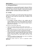
2.4. Refrigerated Spaces
In refrigerated spaces, sensors should be located in the return airflow to
the evaporators on a sidewall (below head-high is preferred), or on the
ceiling, not directly in front of an evaporator. In large rooms with multiple
evaporators, sensors should be mounted on the central line between 2
adjacent evaporators, as turbulence will result in airflows mixing.
2.5. Chillers
In the case of small water- or air-cooled enclosed chiller units mount the
sensor so as to monitor airflow to the extract fans. With larger models
also place a sensor inside the enclosure under or adjacent to the
compressors.
In the case of outdoor units:
•
For enclosed air-cooled chillers or the outdoor unit for
variable refrigerant volume and variable refrigerant flow (VRV/VRF)
systems, mount the sensor so as to monitor airflow to the extract fan.
With large units also place a sensor inside the enclosure under or
adjacent to the compressors.
In the case of non-enclosed outdoor units:
•
If there is an enclosed machinery section locate a sensor there.
•
In the case of units with enclosed compressors, mount sensors in the
enclosures.
•
Where you have protective or acoustic panels mount the sensor low
down under the compressors where it is protected by the panels.
•
With air-cooled chillers or air-cooled condensers with non-enclosed
condenser sections it is difficult to effectively monitor leaks in the coil
sections. With some designs it will be possible using an airflow
sensor to monitor airflow to the start–up fans in the front or rear
sections.
•
If there is a possibility of refrigerant leaks into a duct or air-handling
unit install a sensor to monitor the airflow.
Weatherproof sensors should be used for unprotected outdoor
applications.
Содержание MGS-150
Страница 10: ...MGS 150 Manual 10 6309 9000 Rev 2 Figure 2 EC or IR Sensor Components and Wiring...
Страница 11: ...MGS 150 Manual 6309 9000 Rev 2 11 Figure 3 SC Sensor Components and Wiring...
Страница 17: ...MGS 150 Manual 6309 9000 Rev 2 17 Section 3 Housing Dimensions Figure 4 MGS 150 Standard Housing...
Страница 18: ...MGS 150 Manual 18 6309 9000 Rev 2 Figure 5 IP66 Housing with Splashguard...
Страница 19: ...MGS 150 Manual 6309 9000 Rev 2 19 Figure 6 IP66Airflow Duct Mount Housing Figure 7 Exd Housing Units mm...
Страница 33: ...MGS 150 Manual 6309 9000 Rev 2 33...
Страница 34: ...MGS 150 Manual 34 6309 9000 Rev 2...
Страница 35: ...MGS 150 Manual 6309 9000 Rev 2 35...

