MGS-150 Manual
6309-9000 Rev 2
13
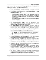
most common leak sources are valves, gauges, flanges, joints (brazed or
mechanical), filling or draining connections, etc.
•
When
mechanical or natural ventilation
is present, mount a
sensor in the airflow.
•
In machinery rooms where there is
no discernable or strong
airflow
then options are:
Point Detection, where sensors are located as near as
possible to the most likely sources of leakage, such as the
compressor, expansion valves, mechanical joints or cable
duct trenches.
Perimeter Detection, where sensors completely surround the
area or equipment.
•
For
heavier-than-air gases
such as halocarbon and
hydrocarbon refrigerants such as R404A, propane, and butane
sensors should be located near ground level.
•
For
lighter-than-air gas
(e.g., ammonia), the sensor needs to
be located above the equipment to be monitored on a bracket or
high on a wall within 12 in (300 mm) of (or on) the ceiling –
provided there is no possibility of a thermal layer trapped under
the ceiling preventing gas from reaching the sensor.
NOTE:
At very low temperatures (e.g., refrigerated
cold store), ammonia gas becomes heavier than air.
•
With similar density or miscible gases (e.g., CO or CO
2)
, sensors
should be mounted about head high (about 5 ft [1.5 m]).
•
Sensors should be positioned just far enough back from any
high-pressure parts to allow gas clouds to form and be detected.
Otherwise, a gas leak might pass by in a high-speed jet and not
be detected by the sensor.
•
Make sure that pits, stairwells and trenches are monitored since
they may fill with stagnant pockets of gas.
•
If a pressure relief vent (PRV) pipe is fitted to the system, it may
be a requirement to mount a sensor to monitor this vent pipe. It
could be positioned about 6 feet (2 m) above the PRV to allow
gas clouds to form.
•
For racks or chillers pre-fitted with refrigerant sensors, these
should be mounted so as to monitor the compressors. If extract
ducts are fitted the airflow in the duct may be monitored.
Содержание MGS-150
Страница 10: ...MGS 150 Manual 10 6309 9000 Rev 2 Figure 2 EC or IR Sensor Components and Wiring...
Страница 11: ...MGS 150 Manual 6309 9000 Rev 2 11 Figure 3 SC Sensor Components and Wiring...
Страница 17: ...MGS 150 Manual 6309 9000 Rev 2 17 Section 3 Housing Dimensions Figure 4 MGS 150 Standard Housing...
Страница 18: ...MGS 150 Manual 18 6309 9000 Rev 2 Figure 5 IP66 Housing with Splashguard...
Страница 19: ...MGS 150 Manual 6309 9000 Rev 2 19 Figure 6 IP66Airflow Duct Mount Housing Figure 7 Exd Housing Units mm...
Страница 33: ...MGS 150 Manual 6309 9000 Rev 2 33...
Страница 34: ...MGS 150 Manual 34 6309 9000 Rev 2...
Страница 35: ...MGS 150 Manual 6309 9000 Rev 2 35...

