background image

MGS-150 Manual 


6309-9000 Rev 2 

WARRANTY POLICY 

BACHARACH, INC. WARRANTS THIS INSTRUMENT, EXCLUDING SENSORS,  TO BE 
FREE FROM DEFECTS IN MATERIALS AND WORKMANSHIP FOR A PERIOD OF TWO 
YEARS FROM THE DATE OF PURCHASE BY THE ORIGINAL OWNER. THE SENSORS 
HAVE A WARRANTY PERIOD OF ONE YEAR FROM THE DATE OF PURCHASE. IF 
THE PRODUCT SHOULD BECOME DEFECTIVE WITHIN THIS WARRANTY PERIOD, 
WE WILL REPAIR OR REPLACE IT AT OUR DISCRETION. 

THE WARRANTY STATUS MAY BE AFFECTED IF THE INSTRUMENT HAS NOT BEEN 
USED AND MAINTAINED PER THE INSTRUCTIONS  IN THIS MANUAL OR HAS BEEN 
ABUSED, DAMAGED, OR MODIFIED IN ANY WAY. THIS INSTRUMENT IS ONLY TO BE 
USED FOR PURPOSES STATED HEREIN. THE MANUFACTURER IS NOT LIABLE FOR 
AUXILIARY INTERFACED EQUIPMENT OR CONSEQUENTIAL DAMAGE. 

DUE TO ONGOING RESEARCH, DEVELOPMENT, AND PRODUCT TESTING, THE 
MANUFACTURER RESERVES THE RIGHT TO CHANGE SPECIFICATIONS WITHOUT 
NOTICE. THE INFORMATION CONTAINED HEREIN IS BASED ON DATA CONSIDERED 
ACCURATE. HOWEVER, NO WARRANTY IS EXPRESSED OR IMPLIED REGARDING 
THE ACCURACY OF THIS DATA. 

ALL GOODS MUST BE SHIPPED TO THE MANUFACTURER BY PREPAID FREIGHT. 
ALL RETURNED GOODS MUST BE PRE-AUTHORIZED BY OBTAINING A RETURN 
MERCHANDISE AUTHORIZATION (RMA) NUMBER. CONTACT THE MANUFACTURER 
FOR A NUMBER AND PROCEDURES REQUIRED FOR PRODUCT TRANSPORT. 

SERVICE POLICY 

BACHARACH, INC. MAINTAINS AN INSTRUMENT SERVICE FACILITY AT THE 
FACTORY.  SOME BACHARACH DISTRIBUTORS / AGENTS MAY  ALSO HAVE 
REPAIR FACILITIES, HOWEVER, BACHARACH ASSUMES NO LIABILITY FOR 
SERVICE PERFORMED BY  ANYONE OTHER THAN BACHARACH PERSONNEL. 
REPAIRS ARE WARRANTED FOR 90 DAYS AFTER DATE OF SHIPMENT 
(SENSORS, PUMPS, FILTERS 

AND BATTERIES HAVE INDIVIDUAL 

WARRANTIES). SHOULD YOUR INSTRUMENT REQUIRE NON-WARRANTY 
REPAIR, YOU MAY CONTACT THE DISTRIBUTOR FROM WHOM IT WAS 
PURCHASED OR YOU MAY CONTACT BACHARACH DIRECTLY. 

IF BACHARACH IS TO DO THE REPAIR WORK, SEND THE INSTRUMENT, 
PREPAID, TO BACHARACH, INC. AT THE FOLLOWING ADDRESS. 

BACHARACH, INC. 
621 HUNT VALLEY CIRCLE 
NEW KENSINGTON, PA 15068 
ATTENTION: SERVICE DEPARTMENT 

ALWAYS INCLUDE YOUR RMA #, ADDRESS, TELEPHONE  NUMBER, CONTACT 
NAME, SHIPPING/BILLING INFORMATION AND A DESCRIPTION OF THE 
DEFECT AS YOU PERCEIVE IT. YOU WILL BE CONTACTED WITH A COST 
ESTIMATE FOR EXPECTED REPAIRS PRIOR TO THE PERFORMANCE OF ANY 
SERVICE WORK. FOR LIABILITY REASONS, BACHARACH HAS A POLICY OF 

Содержание MGS-150

Страница 1: ...Gas Detector Installation and Operation Manual Instruction 6309 9000 Revision 2 February 2013 Product Leadership Training Service Reliability...

Страница 2: ...PPED TO THE MANUFACTURER BY PREPAID FREIGHT ALL RETURNED GOODS MUST BE PRE AUTHORIZED BY OBTAINING A RETURN MERCHANDISE AUTHORIZATION RMA NUMBER CONTACT THE MANUFACTURER FOR A NUMBER AND PROCEDURES RE...

Страница 3: ...SUBJECT TO COPYRIGHT PROTECTION ALL RIGHTS ARE RESERVED NO PARTY MAY USE OR COPY SUCH SOFTWARE IN ANY MANNER OR FORMAT EXCEPT TO THE EXTENT THAT BACHARACH GRANTS THEM A LICENSE TO DO SO IF THIS SOFTW...

Страница 4: ...VRV 15 2 7 Remote Sensor Head Installation 16 Section 3 Housing Dimensions 17 Section 4 Operation and Stabilization 21 Section 5 Configurations 22 5 1 Overview 22 5 2 Adjusting the Alarm Set Point 22...

Страница 5: ...MGS 150 can be used in new buildings areas that require continuous monitoring with high tech gas sensor transmitters to add gas detection solutions to an existing system Typical detection application...

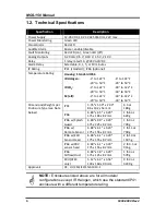
Страница 6: ...to 50 C 40 to 50 C Dimensions Weights per Enclosure Type see Note below IP41 3 35 x 5 59 x 2 09 86 x 142 x 53 mm 6 3 oz 180 g IP66 6 89 x 6 5 x 3 29 175 x 165 x 82 mm 1 lb 6 oz 629 g IP66 w Splash Gua...

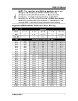
Страница 7: ...t 1 x 1 1 x 2 1 5 x 1 5 2 x 2 Pi x 1 x 1 Area ft 2 1 2 2 25 4 3 14 CFM Ft min Based on CFM and Duct Size 2800 2800 n a n a n a n a 3000 3000 n a n a n a n a 3400 3400 n a n a n a n a 3800 3800 n a n a...

Страница 8: ...ily accessible for visual monitoring and servicing NOTE The monitor must be connected by a marked suitably located and easily reached switch or circuit breaker as means of disconnection NOTE Connect m...

Страница 9: ...bnormalities may arise include the following Plant room maintenance activity involving solvent or paint fumes or refrigerant leaks Accidental gas migration in fruit ripening storage facilities bananas...

Страница 10: ...MGS 150 Manual 10 6309 9000 Rev 2 Figure 2 EC or IR Sensor Components and Wiring...

Страница 11: ...MGS 150 Manual 6309 9000 Rev 2 11 Figure 3 SC Sensor Components and Wiring...

Страница 12: ...d alarm test point TP1 Default factory setting is 50 of the range Time Delay A time delay for the operation of the relay and audible alarm can be selected using jumpers JP5 and JP6 Default factory set...

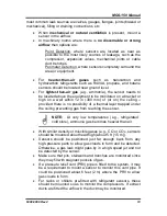
Страница 13: ...in 300 mm of or on the ceiling provided there is no possibility of a thermal layer trapped under the ceiling preventing gas from reaching the sensor NOTE At very low temperatures e g refrigerated cold...

Страница 14: ...rigerant flow VRV VRF systems mount the sensor so as to monitor airflow to the extract fan With large units also place a sensor inside the enclosure under or adjacent to the compressors In the case of...

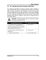
Страница 15: ...have their sensors mounted low e g at less than bed height in the case of an hotel or other similar Category Class A spaces Ceilings or other voids if not sealed are part of the occupied space CAUTION...

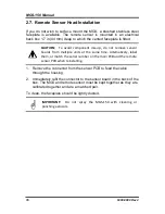
Страница 16: ...ards from multiple units at the same time Alternatively label them or match the serial number on the main PCB and the remote sensor PCB when reinstalling 1 Remove the connector from the sensor PCB to...

Страница 17: ...MGS 150 Manual 6309 9000 Rev 2 17 Section 3 Housing Dimensions Figure 4 MGS 150 Standard Housing...

Страница 18: ...MGS 150 Manual 18 6309 9000 Rev 2 Figure 5 IP66 Housing with Splashguard...

Страница 19: ...MGS 150 Manual 6309 9000 Rev 2 19 Figure 6 IP66Airflow Duct Mount Housing Figure 7 Exd Housing Units mm...

Страница 20: ...0 Rev 2 For Dimensions and Mounting Locations See Figure 5 Figure 8 IP66 Housing with Remote Sensor Head NOTE For the Exd Remote Sensor Head and 16 4 ft 5 m cable the thread varies based on the model...

Страница 21: ...1 5V output o 1 0V on the 2 10V output The typical time for various sensor types to stabilize is shown below Sensor Type Stabilization Time Electrochemical EC 20 30 seconds Semiconductor SC 1 3 minute...

Страница 22: ...378 See Figure 2 and Figure 3 for setting the jumpers Output Decide which output is required 4 20mA 1 5V 0 10V relay outputs etc See Figure 2 and Figure 3 for setting the jumpers 5 2 Adjusting the Ala...

Страница 23: ...ences in environmental conditions IMPORTANT If the MGS is exposed to a large leak it should be tested to ensure correct functionality by electrically resetting the zero setting and carrying out a bump...

Страница 24: ...with locally applicable guidelines and regulations Suitably qualified operators of the unit should be aware of the regulations and standards set down by the industry country for the testing or calibr...

Страница 25: ...the MGS is connected to external systems such as sprinkler systems plant shut down external sirens and beacons ventilation etc and disconnect as instructed by the customer Deactivate alarm delays if s...

Страница 26: ...r a semiconductor or electrochemical sensor is exposed to a substantial gas leak the sensor should be checked and replaced if necessary NOTE To test the audible alarm and or relay function check the d...

Страница 27: ...ampoule so that it sits in the base of the beaker see Figure 10 3 Tighten the wing nut screw onto the ampoule without breaking it 4 Remove the enclosure lid of the gas detector 5 Connect a voltmeter b...

Страница 28: ...ampoule remains from the gas detector and beaker Figure 10 Gas Ampoules for Bump Testing 6 3 Calibration Overview There are two adjustments required zero and span They are monitored at 0V and VS usin...

Страница 29: ...alibrating Semiconductor SC Sensors 1 Locate Pot P2 which is used to adjust the zero point 2 Monitor the output between 0V negative and VS positive 3 Adjust Pot P2 to 0 V or slightly positive 0 01 V i...

Страница 30: ...6 Expose the sensor to calibration gas and allow to stabilize approximately 3 minutes 7 Adjust pot VR202 to the voltage calculated in section 6 4 page 29 6 7 Calibrating Infrared IR Sensors Step Calib...

Страница 31: ...150 to confirm the fault Red light on green led off indicates a fault Sensor may be disconnected from printed circuit board Check to see sensor is properly inserted into board The sensor has been dama...

Страница 32: ...cts are in conformity with the provisions of the following standard s and is in accordance with the following directive s Directive s 2004 108 EC EU EMC Directive 2006 95 EC Low Voltage Directive LVD...

Страница 33: ...MGS 150 Manual 6309 9000 Rev 2 33...

Страница 34: ...MGS 150 Manual 34 6309 9000 Rev 2...

Страница 35: ...MGS 150 Manual 6309 9000 Rev 2 35...

Страница 36: ...l 36 6309 9000 Rev 2 World Headquarters 621 Hunt Valley Circle New Kensington Pennsylvania 15068 Phone 724 334 5000 Toll Free 1 800 736 4666 Fax 724 334 5001 Website www MyBacharach com E mail help My...

Отзывы: