


xvi
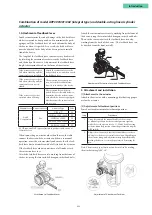
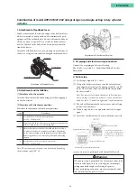
Combination of model AVP200/201/202 (remote type) and double-acting linear cylinder
actuator
1. Attachment of feedback lever
In order to minimize the risk of damage to the feedback lever
while it is carried or transported, and to minimize the pack-
aging as well, the feedback lever is detached from the valve
travel detector when it is packed. As a result, the feedback
lever must be attached to the valve travel detector prior to
installation of the device.
The length of the feedback lever can if necessary be adjusted
by attaching the extension lever between the feedback lever
and the valve travel detector.
Adjustment of the feedback lever length is determined based
on the form of the actuator.
If the actuator type is specified
when ordering, and the
extension lever is included:
Attach the extension lever to the
body of the device, and then attach
the feedback lever.
If the actuator type is specified
when ordering, and the
extension lever is not included:
The extension lever is not necessary.
Attach the feedback lever directly to
the body of the device.
If the actuator type is not
specified when ordering:
The extension lever will be
included. Refer to the table below
to determine, based on the actuator
with which the device is equipped,
whether or not the extension lever
is necessary.
Manufacturer Extension Lever
Actuator Type
Code
Azbil
Corporation
Yes
VP5, 6, 7
Y1
SLOP560, 1000, 1000X
Y2
SLOP1500, 1500X
Y3
DAP560, 1000, 1000X
Y4
DAP1500, 1500X
Y5
(SLOP type and DAP type are limited to products with stroke of
100 mm or less)
When connecting an actuator other than those in the table,
connect the device and the actuator, and then, via manual
operation, move the actuator slowly and ensure that the feed-
back lever does not interfere with a full stroke of the actuator.
If the feedback lever alone cannot cover a full stroke, attach
the extension lever to it.
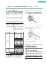
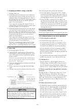
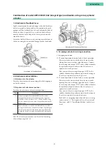
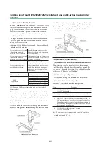
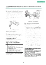
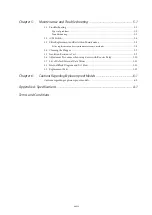
Attach the feedback lever securely, working from the front of
the device, using the two included hexagon socket head bolts.
Attachment of Feedback Lever
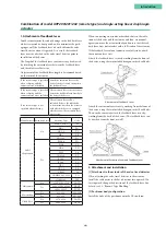
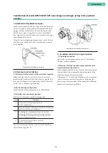
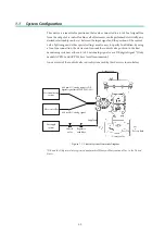
Attach the extension lever securely, working from the front of
the device, using the two included hexagon socket head bolts.
Then, in the same way, attach the feedback lever securely,
working from the back of the device. (The feedback lever can
be attached from the front as well.)
Attachment of Extension Lever and Feedback Lever
2. Attachment and installation
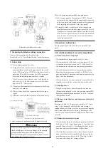
[1] Attachment to the actuator of the valve travel detector
When attaching the valve travel detector to the actuator,
install the cable outlet such that it does not face upward. If it
faces upward, change the direction of the feedback lever. For
details, see 2.3, “Remote Type Handling.”
[2] Positioner body configuration
Install the body of the positioner onto the 2B stanchion.
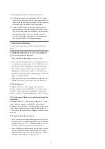
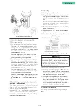
[3] Adjustment of attachment positions
Procedure for adjustment of attachment positions
Step
Procedure
1
Set the A/M switch to manual operation.
(See 5.2, “A/M Switch.”)
2
Supply air, and adjust the actuator air pressure such that the
actuator stem reaches the travel midpoint.
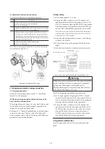
3
Adjust the actuator such that the feedback lever reaches a
90° angle to the valve travel detector's central vertical axis.
Depending on the actuator being used, adjustment may be
performed by moving the valve travel detector, or it may be
performed by moving the pin.
4
Set the A/M switch to automatic operation.
(See 5.2, “A/M Switch.”)
Note: The accuracy specifications can be satisfied by making
the attachment angle 90° ± 2°.
Содержание AVP200
Страница 30: ......
Страница 66: ...2 28...
Страница 80: ...4 4 Menu Tree...
Страница 120: ...5 16...
Страница 128: ...6 8 For models those date of manufacture are before September 2017...
Страница 129: ...6 9 Chapter 6 Cautions regarding Explosion Proof Models For models those date of manufacture are before September 2017...
Страница 130: ...6 10 For models those date of manufacture are before September 2017...
Страница 131: ...6 11 Chapter 6 Cautions regarding Explosion Proof Models For models those date of manufacture are before September 2017...
Страница 132: ...6 12 For models those date of manufacture are before September 2017...
Страница 133: ...6 13 Chapter 6 Cautions regarding Explosion Proof Models For models those date of manufacture are after October 2017...
Страница 135: ...6 15 Chapter 6 Cautions regarding Explosion Proof Models For models those date of manufacture are after October 2017...
Страница 136: ...6 16 For models those date of manufacture are after October 2017...
Страница 138: ...6 18 For models those date of manufacture are after October 2017...
Страница 139: ...6 19 Chapter 6 Cautions regarding Explosion Proof Models For models those date of manufacture are after October 2017...
Страница 184: ...Appendix A Specifications A 25...
Страница 185: ......
Страница 188: ......
Страница 190: ......


