background image

A-20

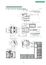
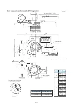
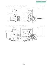
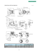
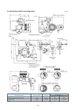
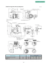
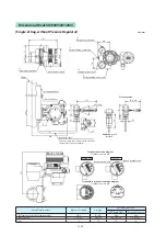
Dimensions (Model AVP200/201/202)

[Single-Acting, without Pressure Regulator] 

unit: mm

187

80

*2

Supply air connection

2B pipe

Auto/manual switch

Mounting bracket

U bolts and nuts

*3

41

41

±4° to ±20°

137

92 to 122

*4

210

Dedicated cable
Fasten properly in accordance with electrical 

equipment technical standards.

21

70

98

42

71

*2

Output air connection

*1

Electrical wiring connection

*1

Electrical wiring connection

*2

Supply air connection

72

46

83

72

Explosion-proof

model

237

Ground terminal screw

Ground terminal screw

Terminal box terminal connection diagram

Terminal screw size: M4

Terminal connection diagram

Terminal screw size: M4

AVP200/202

AVP201

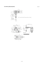
For rotary valve

Main Unit Structure

Electrical conduit

Air pipe

Installation Screws

AVP Main Unit

Position Detector

TIIS flameproof model, regular model

G1/2

Rc1/4

M8

M6

Regular model

1/2NPT

1/4NPT

5/16-18UNC

1/4-20UNC

Notes

*1

*2

*3

*4

Содержание AVP200

Страница 1: ...CM2 AVP300 2001 Smart Valve Positioner 300 Series Model AVP300 301 302 Integral Type 200 Series Model AVP200 201 202 Remote Type User s Manual...

Страница 2: ...criptions in this manual are subject to change without notice It is our hope that this manual is complete and accurate but in the event that there is content which is incomplete or whose accuracy is i...

Страница 3: ...ted to a 4 to 20 mA signal line Since all adjustments can be performed electrically using CommStaff any desired relationship can be set between the input signal and the position of the control valve S...

Страница 4: ...this manual Warning Cases in which it is conceivable that dangerous situations might arise in which the user of the product could be seriously or fatally injured if the product is misused Caution Cas...

Страница 5: ...r very cold When opening the cover of the terminal box be careful of the edges of the cover the threads of the screws on the main unit etc There is a possibility of injury Use a DC power supply that h...

Страница 6: ...R RSA GOM See p v See p xiii Double acting linear cylinder Azbil Corporation actuator model numbers VP SLOP DAP See p vii See p xvi Single acting rotary cylinder actuator for ball valves and butterfly...

Страница 7: ...MC MF Nihon Koso No 270 320 TA TD Yes 400 500 TB TE When connecting an actuator other than those in the table connect the device and the actuator and then switch to manual mode and move the actuator s...

Страница 8: ...ment switch on the upper part of the case UP clockwise to cause the valve to move such that the feed back lever rises upward or turn it DOWN counterclock wise to cause the valve to move such that the...

Страница 9: ...nd the actuator and then via manual operation move the actuator slowly and ensure that the feed back lever does not interfere with a full stroke of the actuator If the feedback lever alone cannot cove...

Страница 10: ...performing auto setup move away from the valve and confirm that the process is safe Check the span point and perform span adjustment 1 Set the input signal to the span point URV Zero ad justment can b...

Страница 11: ...ccuracy specifications can be satisfied by making the attachment angle 90 2 Combination of model AVP300 301 302 integral type and single acting rotary cylinder actuator Adjustment of Attachment Positi...

Страница 12: ...matic module operation confirmation procedure on page 3 9 in this document Check whether the electronics module terminal block is installed correctly in the case on the body of the device 2 If hunting...

Страница 13: ...performed by moving the pin Note The accuracy specifications can be satisfied by making the attachment angle 90 2 Combination of model AVP300 301 302 integral type and double acting rotary cylinder ac...

Страница 14: ...h the lever in the upward direction first set it to reverse close If performing auto setup Rotate in UP direction External zero span adjustment switch 6 If suitable adjustment was not accomplished 1 I...

Страница 15: ...de Azbil Corporation No PSA1 2 PSK1 YS HA1 YA HA2 3 YT HK1 YK VA1 to 3 YQ Yes PSA3 4 YQ PSA6 YL HA4 YN PSA7 Y8 VA4 to 6 YL RSA1 YF RSA2 YU VR1 YV VR2 3 YR VR3H Y6 GOM83S 84S 103S YG GOM124S YM Motoyam...

Страница 16: ...the DOWN direction for Azbil Corporation s VR and RSA actuators for VFR type control valves and hold that position for three seconds Note For reverse close when the valve s fully closed posi tion is...

Страница 17: ...d see 4 4 3 Valve system in this document 3 If the zero point floats or span adjustment cannot be performed Referring to Table 3 1 Integral type setting in 3 1 Auto setup in this document check whethe...

Страница 18: ...and the actuator and then via manual operation move the actuator slowly and ensure that the feed back lever does not interfere with a full stroke of the actuator If the feedback lever alone cannot cov...

Страница 19: ...able follow ap propriate electrical work guidelines 4 Auto setup 1 Set the input signal to 18 1 mA 2 Using a flat blade screwdriver turn the external zero span adjustment switch in the upper part of t...

Страница 20: ...4 Control configuration in this docu ment 3 If the zero point floats or span adjustment cannot be performed Referring to Table 3 1 Integral type setting in 3 1 Auto setup in this document check whethe...

Страница 21: ...justment of attachment positions Procedure for adjustment of attachment positions Step Procedure 1 Set the A M switch to manual operation See 5 2 A M Switch 2 Supply air and adjust the actuator air pr...

Страница 22: ...he upward direction first set it to reverse close If performing auto setup External zero span adjustment switch Rotate in UP direction 6 If suitable adjustment was not accomplished 1 If auto setup doe...

Страница 23: ...vertical axis Note The accuracy specifications can be satisfied by making the attachment angle 90 2 Adjustment of Attachment Positions 3 Air piping and electric wiring connection 1 Air piping connect...

Страница 24: ...e If performing auto setup External zero span adjustment switch Rotate in UP direction 6 If suitable adjustment was not accomplished 1 If auto setup does not operate Check whether the input signal is...

Страница 25: ...et head cap bolts optional Checking specifications The specifications are written on the nameplate on the body of this device Referring to the Appendix confirm that these are as designated In particul...

Страница 26: ...5 If storing the device after being used 1 Prevent humidity from entering the device by attaching the terminal box cover firmly and cover the conduit connection port with tape 2 Prevent humidity and c...

Страница 27: ...g reversing relay 2 10 2 2 4 Electrical Wiring Connection 2 12 2 2 5 Power supply for input signal and travel transmission 2 15 2 2 6 Cables for input signal or travel transmission 2 16 2 3 Remote Typ...

Страница 28: ...5 1 Device information production number confirmation and modification 4 16 4 5 2 Device software revision information confirmation 4 17 4 6 Maintenance 4 18 4 6 1 Mode 4 18 4 6 2 Input calibration 4...

Страница 29: ...maintenance methods 5 8 5 4 Cleaning the Flapper 5 9 5 5 Insulation Resistance Test 5 9 5 6 Adjustment Procedure when using device with Booster Relay 5 10 5 7 List of Default Internal Data Values 5 1...

Страница 30: ......

Страница 31: ...f this chapter This chapter describes the configuration of the control system used by this device The input output system structure of the device is described The structure and the names and functions...

Страница 32: ...the control valve position to the host monitoring system as either a 4 to 20 mA analog signal or as a DE digital signal Only models AVP301 and AVP201 have travel transmission An overview of the contro...

Страница 33: ...y of device settings and self diagnostic results to the host monitoring device set up the digital output system Output format switching The output format provided by the device is specified by the use...

Страница 34: ...al transmission In this system structure the digital signals in the DE protocol transmitted from the de vice are output to a monitoring system that is capable of directly inputting these signals Figur...

Страница 35: ...tch Supply air pressure gauge External ground terminal Reversing relay supply air connection Output air connection OUT2 Mounting plate optional Feedback lever Body Terminal box cover Output air pressu...

Страница 36: ...y goes to this connection Labeled SUP Output air connection The output air is delivered from this connection to the actuator Labeled OUT Mounting plate optional Used to mount the device on the actuato...

Страница 37: ...Houses an input signal controller output terminal an output signal travel transmis sion terminal and an internal ground terminal The structure of the terminal box is shown below Figure 1 6 Structure o...

Страница 38: ...al Figure 1 5 2 Ground this pin in accordance with the specifications Internal ground terminal When using the device use either the internal or external ground terminal Conduit connection 1 Port for w...

Страница 39: ...e is a danger that the surface of the device may be very hot or very cold When opening the cover of the terminal box be careful of the edges of the cover the threads of the screws on the main unit etc...

Страница 40: ...ibed in terms of the vibration at the positioner 2 1 2 Instrumentation air Since this device employs a flapper nozzle structure in the electro pneumatic module if the instrumentation air is dirty or c...

Страница 41: ...regulator mist separator AW30 series filtration rate 5 m AFM30 series filtration rate 0 3 m l Products produced by CKD Corporation Oil mist filter M1000 and M3000 series Mantle S type filtration rate...

Страница 42: ...accessories differ depending on the specifi cations actuator type Be sure to use those that are appropriate for the actuator to be installed When installing the control valve leave as much space as po...

Страница 43: ...xagonal bolt Spring washer Flat washer Mounting plate AVP with toothed washer Hexagonal stud Pointer Connector pin assembly Flange bolt with hexagonal hole Yoke connection Pin Spring Feedback lever Mo...

Страница 44: ...following points must be observed when connecting the device s feedback lever and the actuator s feedback pin Be sure to connect these correctly 1 Only a 6 mm diameter pin may be used 2 The pin shoul...

Страница 45: ...moving the pilot relay cover at the back of the main unit Before mounting the positioner on the actuator consider a design for the mounting bracket and feedback mechanism that leaves sufficient mainte...

Страница 46: ...itioner Install the regulator as close as possible to the body of the positioner The control valve can be operated manually by using this regulator in conjunction with the A M switching function Not p...

Страница 47: ...the diagram below The dimensions of the screws for the connections can be selected based on the specifications Figure 2 7 Air Piping Connection Note When connecting a solenoid valve air valve or the...

Страница 48: ...is expressed in the fol lowing formula OUT2 PSUP OUT1 Reversing relay attachment Detach the dustproof plug on the air piping connection Using sealing tape connect the joint of the reversing relay to...

Страница 49: ...ints Installing a model KZ03 pressure regulator with filter or other pressure regulator with filter separate from the body of the device Using a T connector or the like separate the output air pressur...

Страница 50: ...e pipes Flush the pipes sufficiently before connecting them checking for burrs and other problems Make sure that the output air piping is only as long as necessary 4 When all piping has been completed...

Страница 51: ...s of electrical wiring There are two types of electrical wiring differing based on the purpose of the system Systems that do not use a position signal two line connection Systems that use a position s...

Страница 52: ...osition Signal Four Line Cable Figure 2 15 2 Wiring for Systems Using a Position Signal Two Line Cable If the receiver is a voltage input 1 to 5 V device use the wiring below Figure 2 15 3 Wiring if R...

Страница 53: ...5 mA or greater signal if the flow pressure fluctuates greatly when the valve is fully closed overshoot may occur at the first startup To suppress overshoot temporarily lower the input signal to 0 mA...

Страница 54: ...cable length is 1500 m Use the appropriate remote cable for the wiring between the main unit and the valve travel detector of the remote type model AVP200 201 Cabling When cabling between the device a...

Страница 55: ...rproof the conduit so that rainwater and the like does not penetrate inside Note We recommend the use of silicone resin based non hardening sealant materials 7 After attaching and sufficiently closing...

Страница 56: ...land 2 Insert the remote cable into the terminal box connection on the positioner body 3 Connect the cable and terminal as written on the rear surface of the cover of the terminal box avoiding erroneo...

Страница 57: ...the RAV1 25 4 crimp terminals wire diameter 1 25 mm M4 round crimp terminals with an appropriate crimping tool Figure 2 19 Adjusting the Length of the Cable Caution When connecting or disconnecting p...

Страница 58: ...that fasten the position sensor to the valve travel detector case Figure 2 20 Valve Travel Detector Attachment of valve travel detector Attach the valve travel detector to the prescribed locations on...

Страница 59: ...he control valve the operation of the equipment the safety of the workers etc and ensure that none of these is affected Note Avoid construction methods and installation methods which place the weight...

Страница 60: ...sing it if the orientation of the cable needs to be changed use the flameproof elbow Structure of flameproof cable gland for use at 300 series Figure 2 22 Flameproof Cable Gland Full View O ring Body...

Страница 61: ...ture of flameproof cable gland for use at 200 series main part A full view and exploded view of the flameproof cable gland are shown below Figure 2 24 Flameproof Cable Gland Full View Figure 2 25 Flam...

Страница 62: ...w Structure Installation examples The flameproof cable gland and flameproof elbow are mounted on the conduit connec tion of the terminal box as shown in the diagrams below If the flameproof cable glan...

Страница 63: ...ed Refer to the table below and select a packing adaptor whose internal diameter matches the outer diameter of the cable Cable Outer Diameter mm Packing Inner Diameter mm Notes 7 0 to 8 0 8 Provided 8...

Страница 64: ...ot be possible to prevent flames from escaping and causing personal injury Refer ring to the table below select packing that has an internal diameter that is appro priate for the outer diameter of the...

Страница 65: ...terminal box conduit connection until the lock nut meets the conduit connection Note Apply adequate waterproofing to these parts 3 Turn the flameproof universal elbow in the direction that loosens it...

Страница 66: ...2 28...

Страница 67: ...g on the envi ronment in which the device is used there is a danger that the surface of the device may be very hot or very cold When opening the cover of the terminal box be careful of the edges of th...

Страница 68: ...her for previous versions only the fast response priority mode is implemented Stability priority mode mode that gives priority to stability with little overshoot Fast response priority mode mode that...

Страница 69: ...safe setting Warning During auto setup the valve moves from fully closed to fully open Take appropriate measures beforehand to ensure that the movement of the valve will not cause injury or have an ef...

Страница 70: ...mA open 4 mA Reverse Reverse Reverse Closed 4 mA open 20 mA Direct Reverse Up Down Open Closed Direct Closed 20 mA open 4 mA Direct Direct Reverse Closed 4 mA open 20 mA Reverse Direct Front Left Up...

Страница 71: ...zbil Corporation s HA1 type actuator which has a diaphragm capacity of 850 cm3 or operation stroke if less than 14 3 mm If this occurs refer to 4 4 4 Control parameter configuration and manually adjus...

Страница 72: ...ment Direction When the adjustment screw is turned in the clockwise direction the feedback lever moves in the upward direction Figure 3 2 1 Adjusting the Lever in the Upward Direction When the adjustm...

Страница 73: ...o fully open position span point The procedure to adjust the valve to the fully open position span point is shown below Step Procedure 1 Input from a controller constant current supply the preset elec...

Страница 74: ...r pressure is being supplied there are no air leaks The input signal 4 to 20 mA DC is being applied 1 Operation confirmation procedure The operation confirmation procedure for this device is shown bel...

Страница 75: ...stment is o Conse quently EPM balance adjustment is necessary If EPM balance adjustment is not performed appropriately the valve position may vary suddenly and damage the EPM so be sure to have this a...

Страница 76: ...hat electrical wiring of the device has been performed correctly and that the air supply piping of the device has been performed correctly and that there are no air leaks 3 Confirm that the valve oper...

Страница 77: ...r This chapter describes operations that are performed using communication Refer to this chapter for information regarding the basics of operations the relationship between modes and data settings dat...

Страница 78: ...is no 4 to 20 mA DC signal from the controller connect a constant current supply 3 85 to 21 5 mA DC to the input signal terminal When doing so be sure to re move the wires coming from the controller o...

Страница 79: ...ation 4 3 2 Adjustment data confirmation 4 4 Device Configuration and Adjustment 4 4 1 Auto setup 4 4 2 Zero span adjustment 4 4 3 Control valve system configuration 4 4 4 Control parameter configurat...

Страница 80: ...4 4 Menu Tree...

Страница 81: ...t displayed on the HART version 2 Not displayed on the SFN version 3 Not displayed when DE communication selected 4 Enabled when DE communication selected not shown 5 Displayed when Actuator Size is P...

Страница 82: ...describes the functions of the following versions Model AVP300 301 200 201 Azbil software version 3 5 or later Model AVP302 202 HART Version 6 Device revision 1 Software revision 1 or later Azbil soft...

Страница 83: ...lve position 4 Drive Signal Displays the EPM electro pneumatic module drive signal 5 Temperature Displays the positioner internal temperature C 4 3 2 Adjustment data confirmation Select Device Setup B...

Страница 84: ...or size selection 5 Hysteresis difference selection 6 Travel transmission fail safe selection Warning During auto setup the valve moves from fully open Take appropriate measures be forehand to ensure...

Страница 85: ...mplete select Exit on the Zero Adjustment menu 7 The screen for the forced fully closed setting will appear If you have already modified this value return to the original value 8 Select Exit from the...

Страница 86: ...ion from open to closed set this to Direct if the feedback lever moves upward set this to Reverse The procedure for configuring valve action is shown below Step Procedure 1 Select Device Setup Valve S...

Страница 87: ...AM 8 to 4 3 RSA2 3 800 PARAM 9 to 99 VR3 VR3H 5 800 PARAM 0 Set individually Consult with Azbil Corporation service personnel Actuator size configuration procedure Step Procedure 1 Select Device Setup...

Страница 88: ...ter is described below Table 3 Gap Action Type PID Parameters Parameter Parameter Meaning Units P Reciprocal of the in gap proportional band 1 I Inside gap integrated time s D Inside gap differentiate...

Страница 89: ...procedure The procedure for setting the desired electric current input values is shown below Configuration procedure for electric current input values mA for valve fully closed Step Procedure 1 Selec...

Страница 90: ...ned Data 3 Send the modified setting to the device using the transmission button User defined Data This function sets user defined flow rate characteristics conversion data There are 16 data points fo...

Страница 91: ...nt is performed after auto setup has been executed the forced fully open setting will be 1 less than the overstroke percentage The forced fully open and forced fully closed settings have a hysteresis...

Страница 92: ...formation 7 Date HART version only Displays and allows modification of specific dates such as the last configuration date for the device 8 Descriptor HART version only Displays and allows modification...

Страница 93: ...rsal commands supported by model AVP302 202 2 Device Revision HART version only Displays the revision number of the device specific commands supported by model AVP302 202 3 Software Revision HART vers...

Страница 94: ...he controller and the input signal of 4 mA or 20 mA perceived by the device 4 mA electric current input calibration procedure Step Procedure 1 Select Device Maintenance Input Calibration Calibrate 4 m...

Страница 95: ...on Dummy Input Signal 2 Select a dummy input signal 0 50 100 or Other from the Dummy Input Signal menu 3 If you selected Other enter a value 0 to 100 4 To cancel the dummy input signal select Clear fr...

Страница 96: ...6 Load saved settings Returns all of the device s internal data settings to the settings at the time of shipping This is useful when for instance installing the device on a different control valve If...

Страница 97: ...ect the Update Stick Slip menu to execute the update Clear Stick Slip Count Resets the count to zero Select the Clear Stick Slip Count menu to reset the count Stick Slip XY Threshold Displays and allo...

Страница 98: ...atus If the status is Enabled alarms will occur and if the status is Disabled alarms will not occur 4 7 3 Cycle Count Counts the total number of times that the valve position reverses after at least t...

Страница 99: ...modify the following item Travel Segmentation 1 to Travel Segmentation 16 Displays and allows modification of the 15 position regions for the 16 positions 4 7 5 0 Travel Error When the valve is fully...

Страница 100: ...7 7 Max Travel Speed The maximum operating speed per unit time of the valve Select Diagnostics Valve Diagnostic Information Max Travel Speed You will be able to check or modify the following items To...

Страница 101: ...abled disabled status If the status is Enabled alarms will occur and if the status is Disabled alarms will not occur 4 7 9 Temperature Alarm Select Diagnostics Valve Diagnostic Information Temperature...

Страница 102: ...ailure 4 8 2 Device Status Select Diagnostics Positioner Diagnostic Status Device Status You will be able to check the status conditions shown below If the value of this item is ON a failure was obser...

Страница 103: ...0 Tvl Error Alarm occurs when there is downward deviation between current 0 travel angle and initial 0 travel angle Shut Off Count Alarm The Shut Off Count Alarm occurs when the total number of valve...

Страница 104: ...m 475 Communicator If Actuator Size is set to Param0 and GE in PID Parameters is set to any value other than 0 0 then even if GE is changed to 0 0 and GP GI and GD are also changed and these settings...

Страница 105: ...ice is used there is a danger that the surface of the device may be very hot or very cold When opening the cover of the terminal box be careful of the edges of the cover the threads of the screws on t...

Страница 106: ...lem has arisen in the operation of the device and if no action is taken damage to the device itself may result Should a serious problem occur during operation of the device the output air pressure pos...

Страница 107: ...e stem moves smoothly Check whether there is galling or hardening of the valve packing 2 Check whether there are any errors in the device s internal data settings In particu lar check actuator size hy...

Страница 108: ...al load satisfy the specifications 5 Has wiring been carried out correctly for the respective models for which the travel transmission function is not included models AVP300 302 and AVP200 202 and for...

Страница 109: ...rn the external zero span adjustment screw to the center position HI LO EPM OUT The EPM drive signal exceeds the normal operating range Check whether forced fully open closed feature is working Check...

Страница 110: ...air pressure is output directly from the positioner Manual operation can be performed using the pressure regulator Not available when a double acting actuator is used Warning When the A M switch is o...

Страница 111: ...de screwdriver Confirm the change using an output air pressure gauge Procedure for switching from manual to automatic operation The procedure for switching from manual operation to automatic operation...

Страница 112: ...n removing the screws be careful not to drop the washers corrugated washers etc from the A M switch cover plate 3 Rotate the A M switch in the MAN direction 4 Use nippers or the like to cut the holder...

Страница 113: ...r only under conditions that that will neither cause personal injury nor affect plant operation even if the valve should move suddenly 5 5 Insulation Resistance Test Caution As a rule do not perform t...

Страница 114: ...h the booster sensitivity reduced When using other booster relays as well first reduce the sensitivity Temporarily turn off the input signal and then reduce the sensitivity further by rotating the boo...

Страница 115: ...AVY PID parameter parameter 0 P 1 200 I 4 000 D 0 5000 GE 0 000 GP 0 7000 GI 4 000 GD 0 5000 Flow characteristics LINEAR User defined flow characteristics data Pressure balance type adjustment valve A...

Страница 116: ...5 12 5 8 Internal Block Diagram and I O Flow Internal Block Diagram Figure 5 2 Internal Block Diagram I O Flow Figure 5 3 I O Flow...

Страница 117: ...uly 2003 2 80377921 002 Products shipped starting August 2003 2 7 Flameproof universal elbow G1 2 For model AVP30_ 80357206 108 1 For model AVP20_ 80357206 109 1 8 Lever 80377148 001 1 9 Arm spring 80...

Страница 118: ...position detector of AVP200 201 202 with M4 round crimp terminals Waterproof Mounting screw M6 Cable length 3 m 80388709 01100 1 TIIS Flameproof Mounting screw M6 Cable length 3 m 80388709 02100 1 Wat...

Страница 119: ...r and O rings 3 24 Phillips head screw with spring washer and flat washer 25 Phillips head screw with spring washer 26 Plate 27 Filter 28 Holder 29 Collar A M screw 30 Wave washer A M screw 31 O ring...

Страница 120: ...5 16...

Страница 121: ...al box be careful of the edges of the cover the threads of the screws on the main unit etc There is a possibility of injury Use a DC power supply that has overload protection An overload can cause the...

Страница 122: ...hile the device is turned on and for one minute after it is turned off Doing so can cause an explosion to occur Caution Be sure to install the specified the provided flameproof cable gland on the sign...

Страница 123: ...r Caution In accordance with NEC provisions at the device s signal line exit ports be sure to perform electrical conduit piping work using FM certified sealing fittings When doing this work make sure...

Страница 124: ...can be provided with a sealing fitting approved for Class I locations The sealing compound must be approved and must not have a melting point of less than 93 C 200 F The minimum thickness of the seali...

Страница 125: ...are not required to be explosion proof 4 Class II Division 2 locations 4 1 Wiring methods Rigid metal conduit intermediate metal conduit electrical metallic tubing dust tight wireways Type MC or MI ca...

Страница 126: ...orm electrical wiring work in accordance with NEC Gases with an ignition point of 135 C or higher Ambient atmosphere of acetylene ethylene propane etc ambient atmosphere of metal dust coal or carbon b...

Страница 127: ...Model AVP302 12 02 Vmax 30 V Imax 100 mA Pi 1 W Ci 0 07 F Li 0 22 mH Travel transmission circuit Model AVP301 Vmax 30 V Imax 100 mA Pi 1 W Ci 0 07 F Li 0 22 mH For models those date of manufacture ar...

Страница 128: ...6 8 For models those date of manufacture are before September 2017...

Страница 129: ...6 9 Chapter 6 Cautions regarding Explosion Proof Models For models those date of manufacture are before September 2017...

Страница 130: ...6 10 For models those date of manufacture are before September 2017...

Страница 131: ...6 11 Chapter 6 Cautions regarding Explosion Proof Models For models those date of manufacture are before September 2017...

Страница 132: ...6 12 For models those date of manufacture are before September 2017...

Страница 133: ...6 13 Chapter 6 Cautions regarding Explosion Proof Models For models those date of manufacture are after October 2017...

Страница 134: ...70 22 0 26 0 78 2 09 70 7 50 28 00 57 90 24 0 21 0 63 1 67 80 6 00 22 00 44 40 26 0 17 0 51 1 37 90 5 00 18 00 35 10 28 0 14 0 43 1 14 100 4 00 15 00 28 50 30 0 12 0 36 0 97 110 3 00 12 00 23 60 32 0...

Страница 135: ...6 15 Chapter 6 Cautions regarding Explosion Proof Models For models those date of manufacture are after October 2017...

Страница 136: ...6 16 For models those date of manufacture are after October 2017...

Страница 137: ...01 2 70 60 10 00 40 00 78 70 22 0 26 0 78 2 09 70 7 50 28 00 57 90 24 0 21 0 63 1 67 80 6 00 22 00 44 40 26 0 17 0 51 1 37 90 5 00 18 00 35 10 28 0 14 0 43 1 14 100 4 00 15 00 28 50 30 0 12 0 36 0 97...

Страница 138: ...6 18 For models those date of manufacture are after October 2017...

Страница 139: ...6 19 Chapter 6 Cautions regarding Explosion Proof Models For models those date of manufacture are after October 2017...

Страница 140: ...ds suitable for 5 C above surrounding ambient temperature 4 3 Cables glands or conduit sealing devices used must be certified for the explosion protection mentioned above in item 1 and suitable for th...

Страница 141: ...te de l environnement 4 3 Les presse toupes ou les dispositifs d tanch it des conduits qui sont utilis s doivent tre certifi s pour la protection contre les explosions comme d crit pr c demment au par...

Страница 142: ...von 5 C und dar ber geeigneten Kabel und Kabelverschraubungen verwenden 4 3 Kabelverschraubungen oder Kabelrohrdichtungen m ssen entsprechend dem oben unter Posten 1 genannten Explosionsschutz zertifi...

Страница 143: ...cavi in dotazione idonei per temperatura ambiente al di sopra di 5 C 4 3 I passacavi e i dispositivi di sigillatura dei condotti utilizzati devono essere certificati per la protezione contro le esplos...

Страница 144: ...geschikt zijn voor een temperatuur die 5 C hoger is dan de omgevingstemperatuur 4 3 Kabelwartels of doorvoerdichtingssystemen moeten gecertificeerd zijn voor de explosiebeveiliging vermeld onder punt...

Страница 145: ...C 4 3 Os empaques de cabos ou dispositivos de veda o de conduto utilizados precisam ser certificados para prote o contra explos o mencionada acima no item 1 e ser convenientes para a temperatura de a...

Страница 146: ...r a 5 C 4 3 Los collarines de cables y los dispositivos de cierre de los conductos usados deben tener la certificaci n de protecci n antideflagrante mencionada en el punto 1 y ser adecuados para la te...

Страница 147: ...on in explosive atmospheres caused by air dust mixtures 1 the surface temperature is determined for a dust layer with a thickness of 5 mm maximum 2 conduit or cable glands must be selected and used in...

Страница 148: ...e product be sure to read this man ual In addition observe the requirements in the following standards GB50257 1996 Code for construction and acceptance of electric devices for explosive environments...

Страница 149: ...017 Input signal circuit Model AVP300 301 Ui 30V Ii 100mA Pi 1W Ci 5nF Li 0 22mH Model AVP302 Ui 30V Ii 100mA Pi 1W Ci 41nF Li 0 22mH Travel transmission circuit Model AVP301 Ui 30V Ii 100mA Pi 1W Ci...

Страница 150: ...mospheres Part 13 Equipment repair overhaul and reclama tion GB3836 15 2000 Electrical apparatus for explosive gas atmospheres Part 15 Electrical in stallations in hazardous area other than mines GB38...

Страница 151: ...cable glands suitable for 5 C above surrounding ambient temperature 4 3 Cables glands or conduit sealing devices used must be certified for the IECEx 4 4 Explosion protection mentioned above in item 1...

Страница 152: ...th a thickness of 5 mm maximum 2 conduit or cable glands must be selected and used in such a way that a degree of protection of IP6x is guaranteed 2 When the enclosure of the Smart Valve Positioner is...

Страница 153: ...guintes s o usados neste manual para alertar a poss veis perigos Advert ncia Denota um potencialmente situa o perigosa que se n o evitou poderia resultar em morte ou dano s rio Precau o Denota uma sit...

Страница 154: ...e a press o de contato seja permanentemente garantida O terminal do cabo deve ser fixado entre arruelas lisas Deve ser assegurado que os condutores de alimenta o sejam adequados para uma temperatura d...

Страница 155: ...6 35 Chapter 6 Cautions regarding Explosion Proof Models 11 EAC flameproof 012 2011 1 SVP AVP300 AVP301 AVP302 2 30852 0 2002 60079 0 1998 30852 1 2002 60079 1 1998 3 4...

Страница 156: ...6 36 12 EAC intrinsically safe 012 2011 1 SVP AVP300 AVP301 AVP302 2 30852 0 2002 60079 0 1998 30852 10 2002 60079 11 1999 3 II 0...

Страница 157: ...6 37 Chapter 6 Cautions regarding Explosion Proof Models 13 CNS flameproof CNS Ex d IIC T6 Gb X 1 2 3 4 5 6 1 2 3 IIC 4 85 5 6 X 40 75 IP66 Zone 1 2 SVP SVP Ex d IIC 1 2NPT M20x1 5...

Страница 158: ...0 1 2 AVP300 Ui 30 V Ii 100 mA Pi 1 W Ci 5 nF Li 0 22 mH Ui 10 V Ii 100 mA Pi 1 W Ci 1 nF Li 0 22 mH AVP301 Ui 30 V Ii 100 mA Pi 1 W Ci 5 nF Li 0 22 mH Ui 30 V Ii 100 mA Pi 1 W Ci 22 nF Li 0 22 mH AV...

Страница 159: ...uitable for 5 C above surrounding atmospheres External grounding connection facility The cable lug should be used so that the conductor with a cross sectional area of at least 4mm2 is secured against...

Страница 160: ...ator 4 L min N or less with steady supply air pressure of 140 kPa 1 4 kgf cm2 and output of 50 5 L min N or less with steady supply air pressure of 280 kPa 2 8 kgf cm2 and output of 50 6 L min N or le...

Страница 161: ...F Li 0 22 mH For travel transmission line Vmax 30 V Imax 100 mA Pmax 1 W Ci 0 07 F Li 0 22 mH Installation should comply with NEC ATEX Flameproof II 2 G Ex db II C T6 Gb 40 C Tamb 75 C IEC IP66 Flamep...

Страница 162: ...performance can be assured by installing an appropriate cable gland CE Marking EN61326 1 2013 EMC EN50581 2012 RoHS Configuration tools Field Communication Software CommStaff Model CFS100 This applie...

Страница 163: ...kPa Air consumption For single acting actuator 4 L min N or less with steady supply air pressure of 140 kPa 1 4 kgf cm2 and output of 50 5 L min N or less with steady supply air pressure of 280 kPa 2...

Страница 164: ...Input circuit terminals IIN Model AVP300 301 12 02 Vmax 30 V Imax 100mA Pi 1 W Ci 18 26 nF Li 0 22 mH Model AVP302 12 02 Vmax 30 V Imax 100 mA Pi 1 W Ci 41 nF Li 0 22 mH Output circuit terminals OUT...

Страница 165: ...ls IOUT Model AVP301 Ui 30 V Ii 100 mA Pi 1 W Ci 3 nF Li 0 2 mH Note IP66 waterproof and dust proof performance can be assured by installing an appropriate cable gland CNS Flameproof Ex d IIC T6 Gb X...

Страница 166: ...ening Custom user characteristics 15 segments Manual operation Auto Manual external switch For single acting actuator only Supply air pressure 140 to 700 kPa Air consumption For single acting actuator...

Страница 167: ...r travel transmission type model AVP201 Stroke coverage 14 3 to 100 mm Stroke Feedback Lever Angle 4 to 20 Enclosure classification JIS C0920 watertight Configuration tools Field Communication Softwar...

Страница 168: ...W IECEx Flameproof 1 4 NPT 1 2 NPT J IECEx Flameproof 1 4 NPT M20 1 5 G INMETRO Flameproof 1 4 NPT 1 2 NPT 3 INMETRO Flameproof 1 4 NPT M20 1 5 2 EAC Flameproof 1 4 NPT M20 1 5 7 EAC Intrinsically sa...

Страница 169: ...US304 D 8 9 Mounting bracket for attachment to actuator 7 No mounting plate X X Single acting actuators PSA1 PSA2 PSK1 Y S New model of PSA3 PSA4 VA1 to VA3 produced after 2000 4 Y Q PSA3 PSA4 for exi...

Страница 170: ...15 18 with side manual MF Masoneilan type 35002 series Camflex II 41 2 6 Valve size 1 inch 4 inches MG Masoneilan type 35002 Camflex II 7 Valve size 6 inches 12 inches MH Fisher 657 667 series size 40...

Страница 171: ...s B 4 B4 KITZ B series B 5 B5 KITZ B series B 6 B6 Xomox EL O MATIC E25 40 65 100 200 350 RA Xomox EL O MATIC E600 950 1600 P2500 P4000 RB Tomoe Valve Z series Z 06 08 11 13 EA Tomoe Valve T matic 3I...

Страница 172: ...e parameter of AVP Unless otherwise specified the Smart Valve Positioner will be shipped in the following configuration Input control signal 4 to 20 mA The minimal span for custom range 4 mA Output ch...

Страница 173: ...n feedback lever 9 11 G L GOM810L GOM810LM Springless horizontal with restoration feedback lever 9 11 G M GOM1210L GOM1210LM Springless horizontal with restoration feedback lever 9 11 G N GOM1510L GOM...

Страница 174: ...series 280 330 400 TG Masoneilan 37 38 series 9 11 MA Masoneilan 37 38 series 13 MB Masoneilan 37 38 series 15 18 MC Masoneilan 37 38 series 15 18 with side manual MF Masoneilan type 35002 series Camf...

Страница 175: ...air Valve and Control Japan AW20 1 KT KITZ B series B 2 1 B2 KITZ B series B 3 1 B3 KITZ B series B 4 1 B4 KITZ B series B 5 1 B5 KITZ B series B 6 1 B6 Xomox EL O MATIC E25 40 65 100 200 350 1 RA Xom...

Страница 176: ...With 40 mm extension lever 187 3 Output air pressure connection 3 Output air pressure connection 82 5 18 124 15 6 13 1 With 40 mm extension lever 74 180 6 Connector pin 52 110 40 220 Attach such that...

Страница 177: ...tion 3 Output air pressure connection 82 5 18 124 15 6 13 1 With 40 mm extension lever 74 180 6 Connector pin 52 110 40 174 220 Attach such that when the lever is horizonal the connector pin is within...

Страница 178: ...Appendix A Specifications A 19 For double acting actuator without KZ03 regulator unit mm For double acting actuator with KZ03 regulator unit mm 70 138 145 180 82 41 5 220 150 97 138 179 180 82 270 150...

Страница 179: ...ction 1 Electrical wiring connection 1 Electrical wiring connection 2 Supply air connection 72 46 83 72 Explosion proof model 237 Ground terminal screw Ground terminal screw Terminal box terminal conn...

Страница 180: ...ection 1 Electrical wiring connection Air set 1 Electrical wiring connection 72 46 83 72 22 Explosion proof model 237 Ground terminal screw Ground terminal screw Terminal box terminal connection diagr...

Страница 181: ...connection Air set 1 Electrical wiring connection 72 46 83 72 22 Explosion proof model 237 Ground terminal screw Ground terminal screw Terminal box terminal connection diagram Terminal screw size M4...

Страница 182: ...OUT1 1 Electrical wiring connection 1 Electrical wiring connection 72 46 83 72 22 Explosion proof model Ground terminal screw Ground terminal screw Terminal box terminal connection diagram Terminal sc...

Страница 183: ...eflection angle U sable range 94 13 46 23 13 85 to 115 22 to 67 50 to 85 122 85 30 30 Note In terms of mechanical operation do not exceed 30 37 1 18 29 44 41 Explosion proof model M6 or 1 4 20 UNC scr...

Страница 184: ...Appendix A Specifications A 25...

Страница 185: ......

Страница 186: ...sibility taking the following matters into consideration 1 Regulations and standards or laws that your Equipment is to comply with 2 Examples of application described in any documents provided by Azbi...

Страница 187: ...t you are required to renew any Azbil Corporation s products every 5 to 10 years unless otherwise specified in specifications or instruction manuals System products field instruments sensors such as p...

Страница 188: ......

Страница 189: ...001 Document Name Smart Valve Positioner 300 Series Model AVP300 301 302 Integral Type 200 Series Model AVP200 201 202 Remote Type User s Manual Date 1st edition Oct 1998 27th edition Sep 2017 Issued...

Страница 190: ......
Отзывы: