AXIS P5635-E Mk II PTZ Dome Network Camera
Setup
•
Mounted PIR sensor
•
Switch relay connected to the gate lock, in this case the switch is normally closed (NC)
•
Connecting wires
Physical connection
1. Remove the plug from the camera’s multi-connector and connect the multicable.
2. Connect the wires from the PIR sensor to the input pin, see
AXIS Multicable C I/O Audio Power
.
3. Connect the wires from the switch to the output pin, see
AXIS Multicable C I/O Audio Power
.
Configure I/O ports
You need to connect the switch relay to the camera in the camera’s webpage. First, configure the I/O ports:
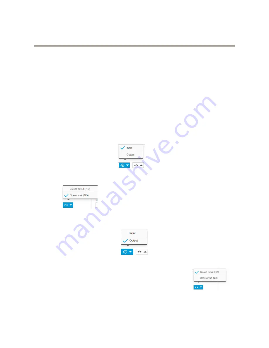
Set the PIR sensor to an input port
1. Go to
System
>
I/O ports
.
2. Select
Input
in the
Port 1
drop-down list.
3. Give the output module a descriptive name, for example “PIR sensor”.
4. To trigger an event whenever the PIR sensor detects something, select
Open circuit
in the drop-down
list.
Set the switch relay to an output port
1. Go to
System
>
I/O ports
.
2. Select
Output
in the
Port 2
drop-down list.
3. Give the output module a descriptive name, for example “Gate switch”.
4. To open the gate whenever an event is triggered, select
Closed circuit
in the drop-down list.
Create the preset position
1. Go to
Settings > PTZ > Preset positions
.
11


