NA-1301 Network Appliance Server Hardware Installation Guide
3.7.1 Serial Ports IRQ Selection
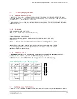
This main board uses two 10-pin connectors for COM1 (CN8) and COM2 (CN7). In general, we use the
COM1 to communicate with LCD module which like as a command channel to LCD module by software
programming. As for the COM2, it should be a console port for this device. Which way can supports
customer doing self test or diagnostic to this device.
Interrupt
Requests on COM1 and COM2 are selected via IRQ4 and IRQ3 respectively. Additionally, both
ports can be enabled or disabled via BIOS setting.
RS-232/422/485 PIN Assignment: CN8,CN7
Description
CN8
CN7
D-SU
B
RS-232 RS-422
RS-485
1
1
Data Carrier
TX-
Data -
2
6
Data Set Ready(DSR)
NC
NC
3 2
Receive
Date(RXD) TX+
Data
+
4 7
Request to Send(RTS)
NC
NC
5 3
Transmit
Data(TXD) RX+
NC
6
8
Clear to Send(CTS) NC
NC
7 4
Data
Terminal
Ready RX-
NC
8 9
Ring Indicator(RI) NC
NC
9 5
GND
GND
GND
10 X
NC
NC
NC
3.8
Installing Keyboard and PS/2 Mouse Connectors
The NA-1301 provides External keyboard (CN32) and Mouse (CN33) interface with two 5-pin
connectors for porting software easily by customer.
Hardware Description
27
Содержание NA-1301
Страница 1: ...NA 1301 Hardware Installation Guide For service person only...
Страница 11: ...NA 1301 Network Appliance Server Hardware Installation Guide 1 4 Dimensions Unit mm Introduction 6...
Страница 16: ...NA 1301 Network Appliance Server Hardware Installation Guide 2 1 1 Main Board Layout Jumpers and Connectors 11...
Страница 25: ...NA 1301 Network Appliance Server Hardware Installation Guide Hardware Description 20...
Страница 36: ...NA 1301 Network Appliance Server Hardware Installation Guide Power Supply Specifications 31...

