EN-1320
OPERATION AND INSTALLATION MANUAL
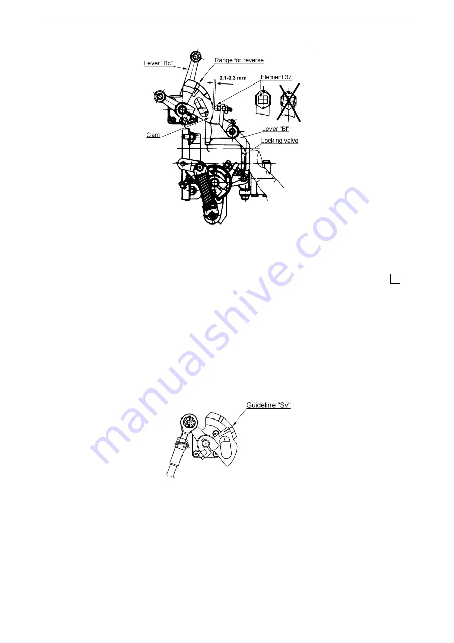
Figure 12-18 Adjustment of axial clearance of blocking valve
i) Adjust the blades by hand so that the beta-ring protruded from the propeller hub and fix it by
appropriate means at distance of 4,5 mm (0.177 inch) from the hub flange. Place the rod "Sv" 65
with yoke onto the gate "Sv" and insert pin into the yoke to go through the gate.
Move the engine condition lever and thus also the lever "Bc" from position "minimum flight pitch" toward
to reverse until you feel drag against movement, when pin touches the gate "Sv".
Check whether guideline on the lever with cam aligns with guideline "Sv" onto the governor scale
(figure 12-19). If the guidelines are not aligned, loosen rod safety nut, which is at yoke side with wrench
"Sv" 1532 924 (from engine toolkit). Place the rod out of the gate "Sv" (figure 12-17) and turn the yoke
in respective direction always at multiple of 180
°
. Repeat the check (yoke is inserted and pin is
installed) and rod length adjustment until the guidelines lowest difference.
Figure 12-19 Rod “Sv” adjustment - scale
j) Tighten the rod nut with wrench "Sv" and secure with lock wire.
k) After adjustment, install nut onto the inserted pin.
l) Secure after basic adjustment check according this section.
61-10-20
PROPELLER CONTROL SYSTEM
(Installation With Jihostroj LUN-Series Governor)
Page 12-17
2017-10-06


