EN-1320
OPERATION AND INSTALLATION MANUAL
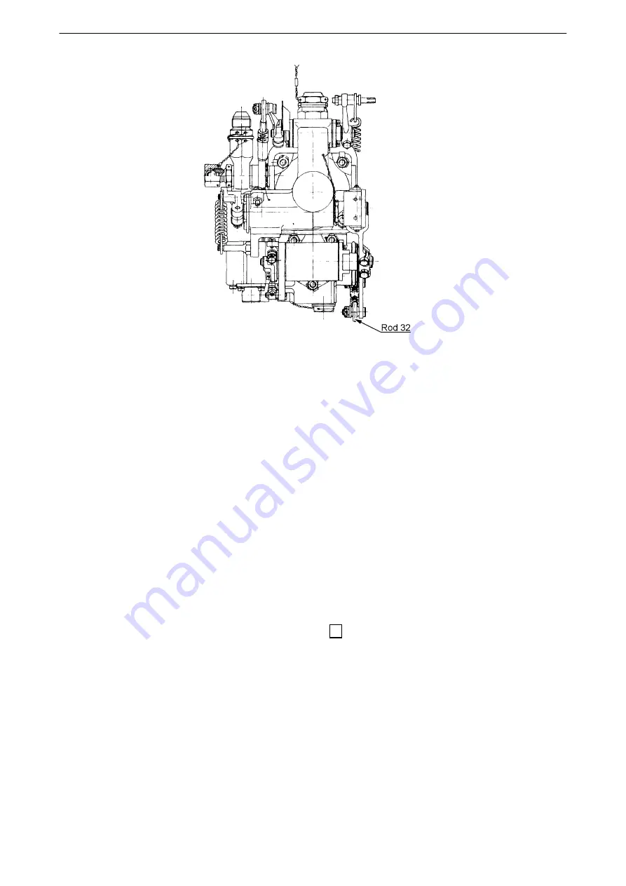
Figure 12-14 Governor LUN7816 View from propeller
(12) Try to turn with drive rod. The rod should rotate freely.
(13) If the propeller is installed, remove carbon block assembly form lever "Zv" (figure 12-6).
CAUTION:
DO NOT INSTALL THE GOVERNOR WITH THE CARBON BLOCK ASSEMBLY INSTALLED WHEN
THE PROPELLER IS INSTALLED.
(14) Use correct and clean packing. Place the governor onto engine gear box. Drive rod gearing must be
correctly inserted into the gear box drive.
(15) Fix the governor using four bolts (figure 12-7) using suitable wrench. A spring washer is at bolt
head and the second washer is inserted into governor flange recess with chamfer facing governor.
Torque the bolts to 20-24 Nm (180-220 in-lbs). Secure at least three bolts using 0,81 mm
(0,032 inch) stainless steel lock wire (figure 12-7).
(16) If the propeller is not in feather, move it to feather by turning blades to move the beta-ring that it seats
at the propeller hub.
CAUTION: CATCH THE BLADES AT ITS SHANK, NEVER AT BLADE TIP.
NOTE:
It is recommended to move the lever "Rn" to feather stop 16, to facilitate servomechanism movement.
(17) Install the carbon block assembly (figure 12-6) onto the lever "Zv" and the beta-ring. Install the washer
onto the pin and safety with cotter pin 1,6 x 10.
CAUTION: Use new cotter pin each installation.
(18) If hydraulic valve LUN7880 and auxiliary pump LUN7840 are installed, follow this procedure:
NOTE: Refer to figure 12-8.
a) Remove the safety wire from the turning screw. Loosen the turning screw to allow rotation of the
fitting. Do not remove.
NOTE:
The turning screw could be modified with the outlet to provide connecting the manometer as
displayed in figure 12-8. This outlet is plugged with the nut and the ball 5/16”. Do not remove this
nut from the turning screw.
61-10-20
PROPELLER CONTROL SYSTEM
(Installation With Jihostroj LUN-Series Governor)
Page 12-13
2017-10-06


