OPERATION AND INSTALLATION MANUAL
EN-1320
NOTE: Install the rod after governor basic adjustment, see section 12.6.
(8) With lever "Rn" at maximum RPM stop 15 , verify lever "Bc" travel from basic position up to reverse,
when the guideline on the lever with cam is against reverse range on the governor scale. Then move
the lever "Bc" further to safety stop.
CAUTION:
THE LEVER "Bc" SHOULD BE FREE. THE LEVER HAS SOME DRAFT AT INITIALIZATION OF THE
LOCKING MECHANISM NO. 37 .
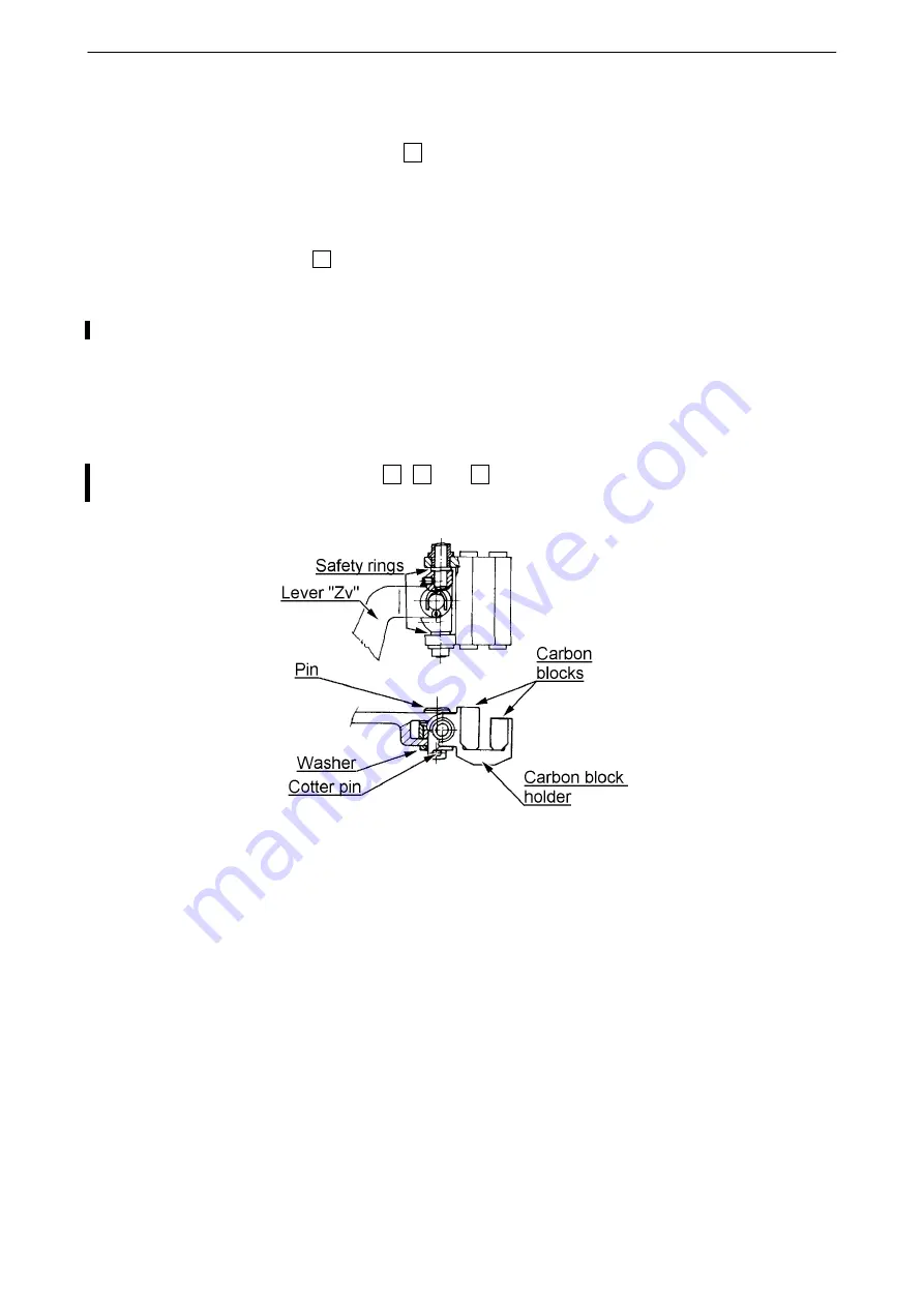
(9) Verify the carbon block assembly (figure 12-6) for damage and completeness.
(10)
Lubricate the carbon block assembly pins with Aeroshell Grease 5, 6 or 22.
WARNING:
REMOVE DAMAGED CARBON BLOCK ASSEMBLY FROM OPERATION!
(11) Verify function of the microswitch "V" (figure 12-3) by moving lever "Zv" in the direction of arrow (figure
12-4).
(12)
Lubricate the bearings of elements 29, 32 and 65, and other appropriate surfaces with Aeroshell
Grease 5, 6 or 22.
Figure 12-6 Carbon block assembly
(13) Verify function of the pilot valve locking by pressing the lever "Bl" (figure 12-3) when the lever "Rn" is at
maximum RPM stop ; after releasing the pilot valve must return to its original position. Perform min.
three times.
(14) Using a lint-free cloth, either dry or lightly dampened with MEK or acetone, clean the governor
flange and the gear box flange.
(15) Insert drive rod into the governor shaft with square inward (figure 12-4). Try to turn with drive rod. The
rod should rotate freely.
CAUTION: THE DRIVE ROD MUST BE IDENTIFIED WITH GOVERNOR S/N.
(16) If the propeller is installed, remove carbon block assembly from lever "Zv" (figure 12-6).
CAUTION:
DO NOT INSTALL THE GOVERNOR WITH THE CARBON BLOCK ASSEMBLY INSTALLED WHEN
THE PROPELLER IS INSTALLED.
61-10-20
PROPELLER CONTROL SYSTEM
(Installation With Jihostroj LUN-Series Governor)
Page 12-6
2019-03-04


