background image

DHN Series Network Video Recorder User Manual 

117 


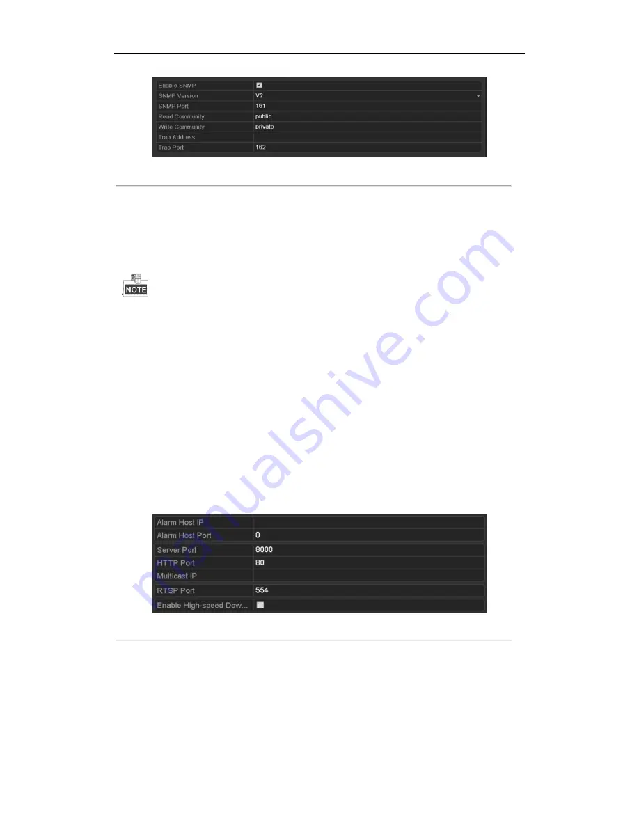
Figure 9. 6


SNMP Settings Interface


3.


Check the 

SNMP 

checkbox to enable this feature. 

4.


Configure the following SNMP settings: 


Trap Address: 

IP Address of SNMP host.


Trap Port: 

Port of SNMP host.


5.


Click the 

Apply

 button to save and exit the interface.   


Before  setting  the  SNMP,  please  download  the  SNMP  software  and  manage  to  receive  the  device 

information via SNMP port. By setting the Trap Address, the NVR is allowed to send the alarm event and 

exception message to the surveillance center. 

9.2.5


Configuring Remote Alarm Host 

Purpose:


With a remote alarm host configured, the NVR will send the alarm event or exception message to the host when an 

alarm is triggered. The remote alarm host must have the Network Video Surveillance software installed. 

Steps: 

1.


Enter the Network Settings interface. 

Menu >Configuration> Network 

2.


Select the 

More Settings 

tab to enter the More Settings interface, as shown in Figure 9. 77. 


Figure 9. 7


More Settings Interface 


3.


Enter 

Alarm Host IP 

and 

Alarm Host Port

 in the text fields.   

The 

Alarm Host IP 

refers to the IP address of the remote PC on which the Network Video Surveillance 

Software is installed, and the 

Alarm Host Port 

must be the same as the alarm monitoring port configured in 

the software. 

4.


Click the 

Apply

 button to save and exit the interface. 

Содержание DHN Series

Страница 1: ...DHN Series Network Video Recorder User Manual REV 20140423...

Страница 2: ...erference received including interference that may cause undesired operation EU Conformity Statement This product and if applicable the supplied accessories too are marked with CE and comply therefore...

Страница 3: ...mended HDD should be used for this device Improper use or replacement of the battery may result in hazard of explosion Replace with the same or equivalent type only Dispose of used batteries according...

Страница 4: ...mpering video exception alert and video loss alert functions Privacy mask Multiple PTZ protocols supported PTZ preset patrol and pattern Zooming in by clicking the mouse and PTZ tracing by dragging mo...

Страница 5: ...full etc Alarm triggers full screen monitoring audio alarm notifying surveillance center sending email and alarm output Automatic restore when system is abnormal Other Local Functions Operable by fro...

Страница 6: ...ion information can be sent to the remote host Remotely start stop recording Remotely start stop alarm output Remote PTZ control Remote JPEG capture Virtual host function is provided to get access and...

Страница 7: ...Live View Mode 31 3 2 1 Front Panel Operation on Live View 31 3 2 2 Using the Mouse in Live View 32 3 2 3 Using an Auxiliary Monitor 33 3 2 4 Quick Setting Toolbar in Live View Mode 33 3 3 Adjusting...

Страница 8: ...Reverse Playback of Multi channel 77 6 3 Picture Playback 78 Chapter 7 Backup 79 7 1 Backing up Record Files 79 7 1 1 Quick Export 79 7 1 2 Backing up by Normal Video Search 81 7 1 3 Backing up by Ev...

Страница 9: ...3 Checking the Network Status 129 9 4 4 Checking Network Statistics 130 Chapter 10 HDD Management 132 10 1 Initializing HDDs 132 10 2 Managing Network HDD 134 10 3 Managing eSATA 136 10 4 Managing HD...

Страница 10: ...ading by FTP 159 12 6 Restoring Default Settings 160 Chapter 13 Additional Features 161 13 1 Configuring RS 232 Serial Port 161 13 2 Configuring General Settings 162 13 3 Configuring DST Settings 163...

Страница 11: ...ctioning normally 2 DVD R W Slot for DVD R W 3 Control Buttons DIRECTION In menu mode the direction buttons are used to navigate between different fields and items and select setting parameters In pla...

Страница 12: ...er numeral 4 Enter letters GHI Exit and back to the previous menu 5 JKL EDIT Enter numeral 5 Enter letters JKL Delete characters before cursor Check the checkbox and select the ON OFF switch Start sto...

Страница 13: ...ion of the composite keys SHIFT are used The light is out when none of the above condition is met ALARM The light is red when there is an alarm occurring HDD Blinks red when HDD is reading writing Tx...

Страница 14: ...the editing text field Upper and lowercase alphabet symbols or numeric input Double press the button to switch the main and auxiliary output 5 Control Buttons DIRECTION In menu mode the direction but...

Страница 15: ...e keys on the remote control closely resemble the ones on the front panel See Table 1 3 Table 1 3 Description of the Soft Keyboard Icons No Name Description 1 POWER Power on off the device 2 DEV Enabl...

Страница 16: ...properly in the remote control And you have to aim the remote control at the IR receiver in the front panel If there is no response after you press any button on the remote follow the procedure below...

Страница 17: ...provider The operation of the mouse Table 1 4 Description of the Mouse Control Name Action Description Left Click Single Click Live view Select channel and show the quick set menu Menu Select and ent...

Страница 18: ...Keyboard 1 Figure 1 5 Soft Keyboard 2 Description of the buttons on the soft keyboard Table 1 5 Description of the Soft Keyboard Icons Icon Description Icon Description Number English letter Lowercas...

Страница 19: ...SATA HDD CD DVD RM 8 Network Interface 1 network interface 9 Termination Switch RS 485 termination switch Up position is not terminated Down position is terminated with 120 resistance 10 RS 485 Inter...

Страница 20: ...output and menu 6 HDMI HDMI video output connector 7 USB Connects USB disks and devices 8 Network Interface Connector for LAN Local Area Network 9 RS 485 Interface Connector for RS 485 devices ALARM...

Страница 21: ...g the device gets the power supply 2 Press the POWER button on the front panel The Power indicator LED should turn blue indicating that the unit begins to start up 3 After startup the Power indicator...

Страница 22: ...zard for Basic Configuration By default the Setup Wizard starts once the NVR has loaded as shown in Figure 2 2 Figure 2 2 Start Wizard Interface Operating the Setup Wizard 1 The Setup Wizard can walk...

Страница 23: ...ck Next button which takes you back to the Network Setup Wizard window as shown in Figure 2 44 Figure 2 4 Network Configuration 7 Click Next button after you configured the network parameters which ta...

Страница 24: ...IP Cameras 11 Click Next button Configure the recording for the searched IP Cameras Figure 2 7 Record Settings 12 Click Copy to copy the settings to other channels as shown in Figure 2 88 Figure 2 8...

Страница 25: ...figuring Network Detection OPTION 1 Steps 1 Right click the mouse when you in the live view mode to show the right click menu Figure 2 9 Right click Menu 2 Select Add IP Camera in the pop up menu to e...

Страница 26: ...3 and 4 of OPTION 1 to add the camera Table 2 2 Explanation of the icons Icon Explanation Icon Explanation Edit basic parameters of the camera Add the detected IP camera The camera is connected you c...

Страница 27: ...Parameters Channel Port If the connected device is an encoding device with multiple channels you can choose the channel to connect by selecting the channel port No in the dropdown list Transfer Proto...

Страница 28: ...ace to enter the protocol management interface Figure 2 15 Protocol Management Interface There are 16 customized protocols provided in the system you can edit the protocol name and choose whether to e...

Страница 29: ...After adding the customized protocols you can see the protocol name is listed in the dropdown list please refer to Figure 2 1616 Figure 2 16 Protocol Setting 3 Choose the protocols you just added to...

Страница 30: ...eters of the camera can t be edited The IP address of the camera can only be edited in the Network Configuration interface see Chapter 9 1 Configuring General Settings for detailed information Figure...

Страница 31: ...icons at the upper right of the screen for each channel showing the status of the record and alarm in the channel so that you can know whether the channel is recorded or whether there are alarms occu...

Страница 32: ...is means if the HDMI is used it will be the main output If the HDMI is not used the VGA output will be the main output See the table below Table 3 2 Priorities of Interfaces HDMI VGA CVBS Main output...

Страница 33: ...t Recording Start continuous recording or motion detection recording of all channels Add IP Camera Enter the IP Camera Management interface and manage the cameras Playback Enter the playback interface...

Страница 34: ...selected from a dropdown list Next Screen When displaying less than the maximum number of cameras in Live View clicking this feature will switch to the next set of displays Playback Enter into Playba...

Страница 35: ...t five minutes If no record is found it means there is no record during the last five minutes Digital Zoom can zoom in the selected area to the full screen You can left click and draw to select the ar...

Страница 36: ...View Settings interface Menu Configuration Live View Figure 3 6 Live View General The settings available in this menu include Video Output Interface Designates the output to configure the settings for...

Страница 37: ...Select a View mode in including 1 4 6 8 16 25 32 36 window division modes are supported 2 Select the small window and double click on the channel number to display the channel on the window You can c...

Страница 38: ...mode and if you want to do some operation you need to enter user name and password tog in again Steps 1 Enter the Shutdown menu Menu Shutdown Figure 3 8 Shutdown 2 Click Logout After you have logged...

Страница 39: ...u control the PTZ camera Before you start Check that the PTZ and the NVR are connected properly through RS 485 interface Steps 1 Enter the PTZ Settings interface Menu Camera PTZ Figure 4 1 PTZ General...

Страница 40: ...e camera to the location where you want to set preset 3 Click the round icon before Save Preset 4 Click the preset number to save the preset Repeat the steps2 4 to save more presets If the number of t...

Страница 41: ...oving on to the next key point The key points are corresponding to the presets The presets can be set following the steps above in Customizing Presets Steps 1 Enter the PTZ Control interface Menu Came...

Страница 42: ...ing the trash icon Select a key point then click or button to adjust the order of the key points Figure 4 6 KeyPoints Deletion 4 2 4 Calling Patrols Purpose Calling a patrol makes the PTZ to move acco...

Страница 43: ...ont panel or click the PTZ Control icon in the quick setting bar to enter the PTZ setting menu in live view mode 2 Choose Patrol on the control bar 3 Double click the patrol or select the patrol and c...

Страница 44: ...e PTZ camera according to the predefined patterns Calling pattern in the PTZ setting interface Steps 1 Enter the PTZ Control interface Menu Camera PTZ More Settings 2 Select the pattern number 3 Click...

Страница 45: ...r the PTZ Settings interface In PTZ control mode the PTZ panel will be displayed when a mouse is connected with the device If no mouse is connected the icon appears in the lower left corner of the win...

Страница 46: ...and initialize it Menu HDD General Figure 5 1 HDD General 2 Check the storage mode of the HDD 1 Click Advanced to check the storage mode of the HDD 2 If the HDD mode is Quota please set the maximum r...

Страница 47: ...file will be deleted You can set the expired time to 0 and then the file will not be deleted The actual keeping time for the file should be determined by the capacity of the HDD Redundant Record Capt...

Страница 48: ...mera 3 Click Apply to save the settings 4 Parameters Settings for Capture 1 Select the Capture tab Figure 5 5 Capture Parameters 2 Configure the parameters 3 Click Apply to save the settings The inter...

Страница 49: ...d capture To schedule the automatic capture you need to choose the Capture tab in the Schedule interface Steps 1 Enter the Record Schedule interface Menu Record Capture Schedule 2 Configure Record Sch...

Страница 50: ...time periods can t be overlapped each other IV Select the record type in the dropdown list To enable Motion Alarm M A motion or alarm M A motion and alarm and VCA Video Content Analysis triggered reco...

Страница 51: ...raw the schedule I Click on the color icons you can choose the schedule type as continuous or event Figure 5 10 Draw the Schedule Descriptions of the color icons are shown in the figure below Figure 5...

Страница 52: ...DHN Series Network Video Recorder User Manual 51 4 Click Apply to save the settings Figure 5 12 Copy Schedule to Other Channels...

Страница 53: ...interface Menu Camera Motion 2 Configure Motion Detection 1 Choose camera you want to configure 2 Check the checkbox after Enable Motion Detection 3 Drag and draw the area for motion detection by mou...

Страница 54: ...ggered recording or capture Steps 1 Enter the Alarm setting interface Menu Configuration Alarm Figure 5 14 Alarm Settings 2 Click Alarm Input Figure 5 15 Alarm Settings Alarm Input 1 Select Alarm Inpu...

Страница 55: ...to the upper level menu Repeat the above steps to configure other alarm input parameters If the settings can also be applied to other alarm inputs click Copy and choose the alarm input number Figure...

Страница 56: ...press the REC SHOT button on the front panel Figure 5 18 Manual Record 2 Enable the Manual Recording 1 Select Record on the left bar 2 Click the status button before camera number to change to 3 Disa...

Страница 57: ...ed 5 6 Configuring Holiday Recording and Capture Purpose Follow the steps to configure the record or capture schedule on holiday for that year You may want to have different plan for recording and cap...

Страница 58: ...the dropdown list There are three different modes for the date format to configure holiday schedule 4 Set the start and end date 5 Click Apply to save settings 6 Click OK to exit the Edit interface 3...

Страница 59: ...5 22 HDD General 2 Select the HDD and click to enter the Local HDD Settings interface 1 Set the HDD property to Redundancy Figure 5 23 HDD General Editing 2 Click Apply to save the settings 3 Click O...

Страница 60: ...gure 5 24 Record Parameters 2 Select Camera you want to configure in the drop down list 3 Check the checkbox of Redundant Record Capture 4 Click OK to save settings and back to the upper level menu Re...

Страница 61: ...de menu 4 Click to enter editing interface 5 Configuring HDD group 1 Choose a group number for the HDD group 2 Click Apply and then in the pop up message box click Yes to save your settings 3 Click OK...

Страница 62: ...k to select a date on the calendar 3 During playback click the button to lock the current recording file In the multi channel playback mde clicking the button will lock all the record files related to...

Страница 63: ...Find the record files you want to protect and then click the icon which will turn to indicating that the file is locked The record files of which the recording is still not completed cannot be locked...

Страница 64: ...save settings and back to the upper level menu You cannot save any files in a Read only HDD If you want to save files in the HDD change the property to R W If there is only one HDD and is set to Read...

Страница 65: ...t playback by channel Steps Choose a channel in live view mode using the mouse and click the button in the quick setting toolbar In the instant playback mode only record files recorded during the last...

Страница 66: ...ording manual or schedule represents event recording motion alarm motion alarm motion alarm VCA Playback progress bar use the mouse to click any point of the progress bar to locate special frames and...

Страница 67: ...les for that camera in that day in the calendar the icon for that day is displayed as Otherwise it is displayed as In the Playback interface The toolbar in the bottom part of Playback interface can be...

Страница 68: ...on Mute Adjust volume Start Stop clipping Capture File lock Add default tag Add customized tag File Management Digital Zoom Pause reverse play Reverse play Single frame reverse play Stop Pause play P...

Страница 69: ...ion detection Steps 1 Enter the Playback interface Menu Playback 2 Select the Event in the drop down list on the top left side 3 Select Alarm Input Motion or VCA as the event type edit the Start time...

Страница 70: ...ar of Playback by Event The indicates the start end time of the record About video type bar represents normal recording manual or schedule represents event recording motion alarm motion alarm motion a...

Страница 71: ...d related information like people and location of a certain time point during playback You are also allowed to use video tag s to search for record files and position time point Before playing back by...

Страница 72: ...terface 2 Choose channels edit start time and end time and then click Search to enter Search Result interface You can enter keyword in the textbox to search the tag on your demand Figure 6 9 Video Sea...

Страница 73: ...bar to locate special frames Table 6 4 Detailed Explanation of Playback by tag Toolbar Button Operation Button Operation Button Operation Button Operation Audio on Mute Adjust volume Start Stop clippi...

Страница 74: ...nts normal recording manual or schedule represents event recording motion alarm motion alarm motion alarm VCA and represents the smart search result Playback progress bar use the mouse to click any po...

Страница 75: ...record file and click button to enter Playback interface If there is no record file at the time point of the log the message box No result found will pop up Figure 6 12 Result of System Log Search 4 P...

Страница 76: ...files in the external devices Steps 1 Enter Playback interface Menu Playback 2 Select the External File in the drop down list on the top left side The files are listed in the right side list You can...

Страница 77: ...ront panel represents playback or reverse playback of one frame 6 2 2 Smart Search Purpose In order to locate events easily and accurately in the playback progress bar you are allowed to analyze a cer...

Страница 78: ...use to draw a red rectangle and the image within it will be enlarged up to 16 times 3 Right click the image to exit the digital zoom interface 6 2 4 Reverse Playback of Multi channel Purpose You can p...

Страница 79: ...els edit start time and end time and then click Search to show searching result 4 Choose a picture you want to view and click button You can click the Back button to back to the search interface 5 The...

Страница 80: ...the channel s you want to back up and click Quick Export button The time duration of record files on a specified channel cannot exceed one day Otherwise the message box Max 24 hours are allowed for q...

Страница 81: ...ing interface until all record files are exported Figure 7 3 Export Finished 3 Check backup result Choose the record file in Export interface and click button to check it The Player player exe will be...

Страница 82: ...o Search for Backup 3 Select record files you want to back up Click to play the record file if you want to check it Check the checkbox before the record files you want to back up The size of the curre...

Страница 83: ...face until all record files are exported with pop up message box Export finished Figure 7 7 Export Finished 5 Check backup result Choose the record file in Export interface and click button to check i...

Страница 84: ...d file if you want to check it Check the checkbox before the record files you want to back up The size of the currently selected files is displayed in the lower left corner of the window 4 Export Clic...

Страница 85: ...using eSATA HDDs Steps 1 Enter Record Advanced and set the usage of eSATA HDD at Export Menu Record Advanced Choose eSATA and set its usage at Export Click Yes when pop up message box System will rebo...

Страница 86: ...ort All button to export all the recording files Or you can select recording files you want to back up and click Export button to enter Export interface Please format the eSATA first when using it for...

Страница 87: ...HDD 7 1 3 Backing up by Event Search Purpose Back up event related record files using USB devices USB flash drives USB HDDs USB writer SATA writer or eSATA HDD Quick Backup and Normal Backup are suppo...

Страница 88: ...Click Details button to view detailed information of the record file e g start time end time file size etc 3 Export Click Export All button to export all the recording files Or you can select recordin...

Страница 89: ...lso select video clips to export directly during Playback using USB devices USB flash drives USB HDDs USB writer SATA writer or eSATA HDD Steps 1 Enter Playback interface Please refer to Chapter 6 1 P...

Страница 90: ...serted USB device is not recognized Click the Refresh button Reconnect device Check for compatibility from vendor You can also format USB flash drive or USB HDDs via the device Figure 7 22 Export Usin...

Страница 91: ...ypes of Captured Pictures Purpose Back up pictures using USB devices USB flash drives USB HDDs USB writer SATA writer or eSATA HDD Steps 1 Enter Export interface Menu Export Picture Select channel s i...

Страница 92: ...etwork Video Recorder User Manual 91 Figure 7 24 Export Pictures Using USB Flash Drive Stay in the Exporting interface until all record files are exported with pop up message Export finished 4 Check b...

Страница 93: ...e recording files Or you can select recording files you want to back up and click Export button to enter Export interface At least one record file shall be selected 3 Backup device management Click Ne...

Страница 94: ...Search for Backup 2 Select record files you want to back up Click Export All button to export all the recording files Or you can select recording files you want to back up and click Export button to...

Страница 95: ...DHN Series Network Video Recorder User Manual 94 Check for compatibility from vendor Figure 7 28 USB Writer Management...

Страница 96: ...device and each working device Set a hot spare device Add a hot spare device on normal device Add the normal device on the hot spare device Start Finish Figure 7 29 Building Hot Spare System 7 4 1 Se...

Страница 97: ...t spare device Figure 7 31 Setting Working Mode for Working device 5 Click the Apply button to save the settings 7 4 3 Managing Hot Spare System Steps 1 Enter the Hot Spare Settings interface of the h...

Страница 98: ...hot spare device will record the video of the IP Camera connected to the working device for backup and the working status of the hot spare device is displayed as Backing up The record backing up can b...

Страница 99: ...DHN Series Network Video Recorder User Manual 98 Figure 7 35 Synchronizing...

Страница 100: ...y Click button and set alarm response actions 3 Click Trigger Channel tab and select one or more channels which will start to record capture or become full screen monitoring when motion alarm is trigg...

Страница 101: ...tion 5 Click Handling tab to set up alarm response actions of motion alarm please refer to Chapter Setting Alarm Response Actions 6 If you want to set motion detection for another channel repeat the a...

Страница 102: ...8 3 Alarm Status Interface of System Configuration 2 Set up the handling action of the selected alarm input Check the Enable checkbox and click Settings button to set up its alarm response actions Fig...

Страница 103: ...ons of the alarm input please refer to Chapter Setting Alarm Response Actions 6 If necessary select PTZ Linking tab and set PTZ linkage of the alarm input Set PTZ linking parameters and click OK to co...

Страница 104: ...DHN Series Network Video Recorder User Manual 103 to copy the settings to them Figure 8 7 Copy Settings of Alarm Input...

Страница 105: ...o set up handling action of video loss 3 Set up arming schedule of the handling actions 1 Select Arming Schedule tab to set the channel s arming schedule 2 Choose one day of a week and up to eight tim...

Страница 106: ...g handling action of the channel Check the checkbox of Enable Video Tampering Detection Drag the sensitivity bar to set a proper sensitivity level Use the mouse to draw an area you want to detect vide...

Страница 107: ...0 Set Arming Schedule of Video Tampering 4 Select Linkage Action tab to set up alarm response actions of video tampering alarm please refer to Chapter Setting Alarm Response Actions 5 Click the OK but...

Страница 108: ...pture or become full screen monitoring when a VCA alarm is triggered and click Apply to save the settings 4 Select Arming Schedule tab to set the arming schedule of handling actions Figure 8 11 Set Ar...

Страница 109: ...ork cable IP Conflicted Duplicated IP address Illegal Login Incorrect user ID or password Record Capture Exception No space for saving recorded files or captured images Hot Spare Exception Disconnecte...

Страница 110: ...xceptions 2 Check the checkbox of Enable Event Hint Figure 8 13 Event Hint Settings Interface 3 Click the to set the type of event to be displayed on the image Figure 8 14 Event Hint Settings Interfac...

Страница 111: ...configuration Email Linkage Send an email with alarm information to a user or users when an alarm is detected Please refer to Chapter 9 2 10 for details of Email configuration Trigger Alarm Output Tr...

Страница 112: ...ove steps to set up arming schedule of other days of a week You can also use Copy button to copy an arming schedule to other days Click the OK button to complete the video tampering settings of the al...

Страница 113: ...the alarm can be cleared only by clicking Clear button in the following interface Steps Select the alarm output you want to trigger or clear and make related operations Menu Manual Alarm Click Trigge...

Страница 114: ...terface you can configure the following settings Working Mode NIC Type IPv4 Address IPv4 Gateway MTU and DNS Server If the DHCP server is available you can click the checkbox of DHCP to automatically...

Страница 115: ...ly button to save and exit the interface 6 After successful settings the system asks you to reboot the device to enable the new settings and the PPPoE dial up is automatically connected after reboot Y...

Страница 116: ...ctable IPServer DynDNS PeanutHull NO IP and HiDDNS IPServer Enter Server Address for IPServer Figure 9 3 IPServer Settings Interface DynDNS 1 Enter Server Address for DynDNS i e members dyndns org 2 I...

Страница 117: ...P address of NTP server NTP Port Port of NTP server 5 Click the Apply button to save and exit the interface The time synchronization interval can be set from1 to 10080min and the default value is 60mi...

Страница 118: ...m Host Purpose With a remote alarm host configured the NVR will send the alarm event or exception message to the host when an alarm is triggered The remote alarm host must have the Network Video Surve...

Страница 119: ...e Software the multicast address must be the same as the NVR s multicast IP Figure 9 8 Configure Multicast 4 Click the Apply button to save and exit the interface The multicast function should be supp...

Страница 120: ...for remote client software access The HTTP port is used for remote web browser access 9 2 9 Configuring HTTPS Port Purpose HTTPS provides authentication of the web site and associated web server that...

Страница 121: ...install the certificate 6 Check the checkbox to enable the HTTPS function 7 Click the Save button to save the settings 9 2 10Configuring Email Purpose The system can be configured to send an Email not...

Страница 122: ...or host name e g smtp 263xmail com SMTP Port No The SMTP port The default TCP IP port used for SMTP is 25 Enable SSL optional Click the checkbox to enable SSL if required by the SMTP server Sender The...

Страница 123: ...s etc You can use the UPnP function to enable the fast connection of the device to the WAN via a router without port mapping Before you start If you want to enable the UPnP function of the device you...

Страница 124: ...ternal port No for server port http port RTSP port and https port respectively You can use the default port No or change it according to actual requirements External Port indicates the port No for por...

Страница 125: ...RTSP port and https port respectively The value of the RTSP port No should be 554 or between 1024 and 65535 while the value of the other ports should be between 1 and 65535 and the value must be diff...

Страница 126: ...p the download of record files through web browser or CMS software If you enable the high speed download function the local menu operation will be affected It is recommended to disable this function a...

Страница 127: ...camera list Configuration Remote Configuration Camera Management IP Camera 5 Click the link and the page of IP camera management appears 9 2 14Telnet Settings Purpose Telnet function provides an easy...

Страница 128: ...obtain real time information of NVR such as linking status MTU sending receiving rate etc Steps 1 Enter the Network Traffic interface Menu Maintenance Net Detect Figure 9 24 Network Traffic Interface...

Страница 129: ...in the text field of Destination Address 4 Click Test button to start testing network delay and packet loss The testing result pops up on the window If the testing is failed the error message box wil...

Страница 130: ...t is incorrect Figure 9 27 Export Network Packet 4 Click Export button to start exporting 5 After the exporting is complete click OK to finish the packet export as shown in Figure 9 2828 Figure 9 28 P...

Страница 131: ...lt If the message box pops out with other information instead of this one you can click Network button to show the quick setting interface of the network parameters 9 4 4 Checking Network Statistics P...

Страница 132: ...l 131 Figure 9 31 Network Stat Interface 3 Check the bandwidth of IP Camera bandwidth of Remote Live View bandwidth of Remote Playback bandwidth of Net Receive Idle and bandwidth of Net Send Idle 4 Yo...

Страница 133: ...starts up if there exits any uninitialized HDD Figure 10 1 Message Box of Uninitialized HDD Click Yes button to initialize it immediately or you can perform the following steps to initialize the HDD...

Страница 134: ...anual 133 Figure 10 4 Status changes to Initializing 5 After the HDD has been initialized the status of the HDD will change from Uninitialized to Normal Figure 10 5 HDD Status Changes to Normal Initia...

Страница 135: ...nterface as shown in Figure 10 710 7 Figure 10 7 HDD Information Interface 3 Add the allocated NetHDD 4 Select the type to NAS or IP SAN 5 Configure the NAS or IP SAN settings Add NAS disk 1 Enter the...

Страница 136: ...sk from the list shown below 4 Click the OK button to add the selected IP SAN disk Up to 1 IP SAN disk can be added Figure 10 9 Add IP SAN Disk 6 After having successfully added the NAS or IP SAN disk...

Страница 137: ...p Refer to Backup using eSATA HDDs in Chapter Backing up by Normal Video Search for operating instructions Record Capture use the eSATA for record capture Refer to the following steps for operating in...

Страница 138: ...Storage Mode 2 Set the Mode to Group as shown in Figure 10 13 Figure 10 13 Storage Mode Interface 3 Click the Apply button and the following Attention box will pop up Figure 10 14 Attention for Reboo...

Страница 139: ...of Chapter Setting HDD Groups A HDD can be set to read only to prevent important recorded files from being overwritten when the HDD becomes full in overwrite recording mode When the HDD property is se...

Страница 140: ...rder User Manual 139 5 In the HDD Information menu the HDD property will be displayed in the list At least 2 hard disks must be installed on your NVR when you want to set a HDD to Redundancy and there...

Страница 141: ...8 The NVR must be rebooted to enable the changes to take effect Figure 10 18 Storage Mode Settings Interface 3 Select a camera for which you want to configure quota 4 Enter the storage capacity in the...

Страница 142: ...e same quota settings You can also click the checkbox of IP Camera to select all cameras 7 Click the OK button to finish the Copy settings and back to the Storage Mode interface 8 Click the Apply butt...

Страница 143: ...A R T detection This function is not supported by DHN 04H series NVR Before you start An eSATA disk should be connected to the device Steps 1 Enter the HDD Advanced Setting interface Menu HDD Advanced...

Страница 144: ...f the clone source disk 4 Check the checkbox of the HDD to be cloned in the Clone Source list 5 Click the Clone button and a message box pops up Figure 10 23 Message Box for Disk Clone 6 Click the Yes...

Страница 145: ...of each HDD which is displayed on the list as shown in Figure 10 25 Figure 10 25 View HDD Status 1 If the status of HDD is Normal or Sleeping it works normally If the status is Uninitialized or Abnorm...

Страница 146: ...DHN Series Network Video Recorder User Manual 145 Figure 10 26 View HDD Status 2...

Страница 147: ...A R T information list as shown in Figure 10 27 Figure 10 27 S M A R T Settings Interface The related information of the S M A R T is shown on the interface You can choose the self test types as Short...

Страница 148: ...ries Network Video Recorder User Manual 147 Figure 10 28 Bad Sector Detection And you can click Error info button to see the detailed damage information And you can also pause resume or cancel the det...

Страница 149: ...or from the dropdown list 3 Click the checkbox s below to select the HDD error alarm type s as shown in Figure 10 29 The alarm type can be selected to Audible Warning Notify Surveillance Center Send E...

Страница 150: ...apply the settings 11 2 Configuring Privacy Mask Purpose You are allowed to configure the four sided privacy mask zones that cannot be viewed by the operator The privacy mask can prevent certain surv...

Страница 151: ...1 3 Configuring Video Parameters Steps 1 Enter the Image Settings interface Menu Camera Image 2 Select the camera to set image parameters 3 You can click on the arrow to change the value of each param...

Страница 152: ...tab to enter the Device Information menu to view the device name model serial No firmware version and encode version as shown in Figure 12 1 Figure 12 1 Device Information Interface 12 1 2Viewing Came...

Страница 153: ...Information menu to view the recording status and parameters of each camera as shown in Figure 12 3 Figure 12 3 Record Information Interface 12 1 4Viewing Alarm Information Steps 1 Enter the System I...

Страница 154: ...work tab to enter the Network Information menu to view the network information as shown in Figure 12 5 Figure 12 5 Network Information Interface 12 1 6Viewing HDD Information Steps 1 Enter the System...

Страница 155: ...DHN Series Network Video Recorder User Manual 154 Figure 12 6 HDD Information Interface...

Страница 156: ...and exported at any time Steps 1 Enter the Log Search interface Menu Maintenance Log Information Figure 12 7 Log Search Interface 2 Set the log search conditions to refine your search including the S...

Страница 157: ...rence source not found 7 Select the backup device from the dropdown list of Device Name 8 Click the Export to export the log files to the selected backup device You can click the New Folder button to...

Страница 158: ...DHN Series Network Video Recorder User Manual 157 Figure 12 10 Log Export Interface 3 You can check the checkbox of the HDD 4 Click the Export button to export all the log files stored in the HDD...

Страница 159: ...evice 4 To import a configuration file select the file from the selected backup device and click the Import button After the importing process is completed you must reboot the NVR 12 4 Importing Expor...

Страница 160: ...e Upgrade button to start upgrading 6 After the upgrading is complete reboot the NVR to activate the new firmware 12 5 2Upgrading by FTP Before you start Configure PC running FTP server and NVR to the...

Страница 161: ...Menu Maintenance Default Figure 12 12 Restore Factory Default 2 Click the OK button to restore the default settings Except the network parameters including IP address subnet mask gateway MTU NIC worki...

Страница 162: ...erial port parameters must be the same as the NVR s when connecting with the PC serial port Transparent Channel Connect a serial device directly to the NVR The serial device will be controlled remotel...

Страница 163: ...standard to NTSC or PAL which must be the same with the video input standard VGA Resolution Select the VGA output resolution which must be the same with the resolution of the monitor screen HDMI Reso...

Страница 164: ...1 Enter the General Settings interface Menu Configuration General 2 Choose DST Settings tab Figure 13 3 DST Settings Interface You can check the checkbox before the Auto DST Adjustment item Or you can...

Страница 165: ...s used for the remote and keyboard control CVBS Output Brightness Adjust the video output brightness Auto Logout Set timeout time for menu inactivity E g when the timeout time is set to 5 Minutes then...

Страница 166: ...User s MAC Address Level Set the user level to Operator or Guest Different user levels have different operating permission Operator The Operator user level has permission of Two way Audio in Remote Co...

Страница 167: ...output Local Shutdown Reboot Shutting down or rebooting the NVR Remote Configuration Remote Log Search Remotely viewing logs that are saved on the NVR Remote Parameters Settings Remotely configuring...

Страница 168: ...rolling PTZ movement of the selected camera s Local Video Export Locally exporting recorded files of the selected camera s 7 Click the OK button to save the settings and exit interface Only the admin...

Страница 169: ...and MAC address Check the checkbox of Change Password if you want to change the password and input the new one in the text field of Password and Confirm Admin You are only allowed to edit password and...

Страница 170: ...namic DNS is a method protocol or network service that provides the capability for a networked device such as a router or computer system using the Internet Protocol Suite to notify a domain name serv...

Страница 171: ...e further process There is an audible warning sound Di Di Di DiDi after a new bought NVR starts up Possible Reasons a No HDD is installed in the device b The installed HDD has not been initialized c T...

Страница 172: ...p 3 If it is solved finish the process If not please contact the engineer from our company to do the further process The IP camera frequently goes online and offline and the status of it displays as D...

Страница 173: ...ideo output interface in the drop down list and configure the window you want to view The view settings can only be configured by the local operation of NVR Different camera orders and window division...

Страница 174: ...Simultaneously press Ctrl and C to exit the ping command 2 Verify the network between NVR and PC is connected 1 Open the cmd window in the Start menu or you can press windows R shortcut key to open it...

Страница 175: ...r multi channel Possible Reasons a Poor network between NVR and IP camera and there exists packet loss during the transmission b The frame rate is not the real time frame rate c The NVR supports up to...

Страница 176: ...al General and verify the Device Time is correct 2 Verify the search condition is correct Select Playback and verify the channel and time are correct 3 Verify the HDD status is normal Select Menu HDD...

Страница 177: ...00227 A1D 220 V3 13 16 AC 1280 1024 ARECONT AV8185DN 65172 1600 1200 AV1305M 65175 1280 1024 AV2155 65143 1600 1200 AV2815 65220 1920 1080 AV3105M 65175 1920 1080 AV5105 65175 1920 1080 AXIS M1114 5 0...

Страница 178: ...8 2 20120327 2 9080 A1 7852 2048 1536 SAMSUNG ONVIF compatibility SNB 5000P V3 10_130416 1280 1024 SANYO VCC HD2300P 2 03 02 110318 00 1920 1080 VCC HD2500P 2 02 02 110208 00 1920 1080 VCC HD4600P 2 0...

Отзывы: