background image

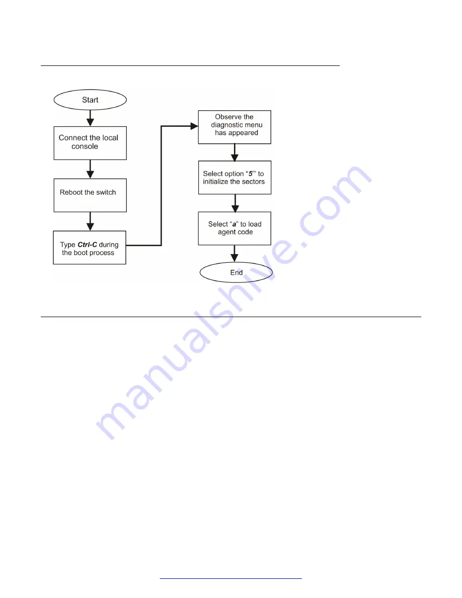
Corruption of flash recovery tree

Incorrect PVID

A loss of communication between a client and a critical server can occur when client ports are
assigned to the wrong VLAN. For example, if the server VLAN is configured as a port-based VLAN,
with a VLAN ID of 3, and the client port VLAN identifier (PVID) is 2, communication between the
client and the server fails. You can prevent this communication failure by setting VLAN configuration
control for the switch to 

autoPVID

.

The PVID associates a switch port with a specific VLAN. For example, a switch port with a PVID of 3
assigns all untagged data frames received on that port to VLAN 3.

Emergency recovery trees

30

     Troubleshooting Avaya VSP 7000 Series

July 2015

Comments on this document? [email protected]

Содержание Virtual Services Platform 7000 Series

Страница 1: ...Troubleshooting Avaya Virtual Services Platform 7000 Series Release 10 4 NN47202 700 Issue 05 01 July 2015 ...

Страница 2: ...ity is specified in the documentation or other materials available to You Software means computer programs in object code provided by Avaya or an Avaya Channel Partner whether as stand alone products pre installed on hardware products and any upgrades updates patches bug fixes or modified versions thereto Designated Processor means a single stand alone computing device Server means a Designated Pr...

Страница 3: ...a problem with your Avaya product or Hosted Service For a list of support telephone numbers and contact addresses go to the Avaya Support website http support avaya com or such successor site as designated by Avaya scroll to the bottom of the page and select Contact Avaya Support Trademarks The trademarks logos and service marks Marks displayed in this site the Documentation Hosted Service s and p...

Страница 4: ... tracing 18 Stack loopback testing 19 Stack health check 19 System logs 19 Configuration file backup 20 ASCII download log 20 CPU and memory utilization 22 Show commands 22 MLT or DMLT 22 SNMP traps 23 Auto Unit Replacement 23 Stack duplicate base unit protection 24 Multicast behavior 24 IPv6 25 LED display 25 Avaya Knowledge and Solution Engine 25 Diagnostics quick mode 26 SFP DDI information 26 ...

Страница 5: ...unit for repair 42 Replacing a unit in the stack 42 Removing a failed unit 43 Verifying the new unit software version 43 Obtaining the correct software version 43 Placing a new unit 44 Connecting stacking cables 44 Returning the unit for repair 44 Chapter 8 Troubleshooting SFP 45 Confirming SFP device support 45 Displaying SFP device details 45 Replacing a SFP device 45 Enabling DDI logging 46 Vie...

Страница 6: ...6 UDP connection 57 Viewing the global IPv6 configuration 57 Viewing IPv6 UDP information 57 Verifying remote host IPv6 UDP application support 58 Unable to assign an IPv6 address to an interface 58 Changing an interface IPv6 address 58 Chapter 10 Troubleshooting IGMP 60 Checking IGMP configuration for a VLAN 60 Chapter 11 Troubleshooting RSTP SNMP traps 61 Viewing the RSTP configuration 61 Verify...

Страница 7: ...aces 84 OSPF router priority 84 An OSPF route is not in the routing table 85 ECMP maximum path for OSPF 85 External route advertisements 86 Switches exchanging RIP packets do not learn routing information 87 Interface send and receive RIP versions 87 RIP interface supply and listen status 87 ECMP maximum path for RIP 88 Learned RIP routes are deleted and learned again 89 Checking the global RIP ti...

Страница 8: ...l router priority 97 Critical IP 97 Virtual router preempt status 98 Checking the VLAN staus 99 VRRP preempt mode does not function 99 Critical IP 99 Virtual router preempt status 100 Chapter 14 Troubleshooting Fabric Attach 101 Verifying FA settings 101 Verifying FA message authentication status 102 Verifying FA per port settings 102 Verifying discovered FA elements 102 Contents 8 Troubleshooting...

Страница 9: ...ce ACLI and Enterprise Device Manager EDM this document focuses on using ACLI to demonstrate most of the troubleshooting tasks You can access ACLI through either a direct console connection to the switch or by using the Telnet or SSH protocols to connect to the switch remotely The troubleshooting topics discussed in this document are provided with the following assumptions You have a basic knowled...

Страница 10: ...shoot Avaya products About this task Videos are available on the Avaya Support website listed under the video document type and on the Avaya run channel on YouTube Procedure To find videos on the Avaya Support website go to http support avaya com and perform one of the following actions In Search type Avaya Mentor Videos to see a list of the available videos In Search type the product name On the ...

Страница 11: ...es of a particular feature Use this procedure to perform an index search of your documentation collection Before you begin Download the documentation collection zip file to your local computer You must have Adobe Acrobat or Adobe Reader installed on your computer Procedure 1 Extract the document collection zip file into a folder 2 Navigate to the folder that contains the extracted files and open t...

Страница 12: ...ocumentation for a specific product for example Application Technical Notes for Ethernet Routing Switch 8800 Procedure 1 In an Internet browser go to https support avaya com 2 Type your username and password and then click Login 3 Under My Information select SSO login Profile 4 Click E NOTIFICATIONS 5 In the GENERAL NOTIFICATIONS area select the required documentation types and then click UPDATE 6...

Страница 13: ...ct the product name 9 Select a release version 10 Select the check box next to the required documentation types 11 Click Submit Related resources July 2015 Troubleshooting Avaya VSP 7000 Series 13 Comments on this document infodev avaya com ...

Страница 14: ...eature see the following Configuring Avaya Fabric Connect on Avaya Virtual Services Platform 7000 Series NN47202 510 Verifying FA settings on page 101 Verifying FA message authentication status on page 102 Verifying FA per port settings on page 102 Verifying discovered FA elements on page 102 Unknown multicast filtering IGMP unknown multicast filtering is no longer supported on the Avaya Virtual S...

Страница 15: ...h part of your network for problems Know how your devices are connected logically and physically with virtual local area networks VLAN Maintain online and paper copies of your device configuration information Ensure that all online data is stored with the regular data backup for your site If your site has no backup system copy the information to a backup medium and store the backup off site Store ...

Страница 16: ...me to obtain sufficient statistics and data to see patterns in the traffic flow for example which devices are typically accessed or when peak usage times occur You can speed up the process of isolating network problems by using a baseline analysis as an indicator of overall network health A baseline view of network traffic behavior during normal operation is an important reference that you can com...

Страница 17: ...sed Although you can configure the switch to monitor both ingress and egress traffic the following restrictions apply for port based and address based port mirroring For Xtx mode you can only configure one port as the monitor port and one port as the mirrored port monitoring traffic transmitted by port X For Xrx mode you can only configure one port as the monitor port and one port as the mirrored ...

Страница 18: ...ackProbe or equivalent Unlike other methods that are used to analyze packet traffic with port mirroring a copy of the packet can be captured and analyzed so the packet traffic is uninterrupted and packets flow normally through the mirrored port For information about configuring port mirroring using ACLI or EDM see Configuring System Monitoring on Avaya Virtual Services Platform 7000 Series NN47202...

Страница 19: ...ack loopback testing see Configuring System Monitoring on Avaya Virtual Services Platform 7000 Series NN47202 505 Stack health check You can use the stack health check feature to run a high level test to confirm stack operation and stack continuity Stack health check results provide you with information about the Fabric Interconnect port status for each stack switch unit the total number of switch...

Страница 20: ...check the system log for messages indicating that a configuration block is corrupted The following are examples of messages the switch can forward to the system log for a corrupt configuration file Error loading primary configuration block block number Error loading backup configuration block block number Backup configuration block block number is in use Configuration files are corrupted Restored ...

Страница 21: ...the question mark character Success ACG_DOWNLOAD_OK Indicates that the connection was successful The ASCII configuration file can be accessed and it can be used The IP address and the filename are in the message when you use the TFTP server or just the filename is in the message if you use a USB device Success on load on boot ACG_DOWNLOAD_OK_ON_BOOT Indicates that the connection was successful at ...

Страница 22: ... Configuring System Monitoring on Avaya Virtual Services Platform 7000 Series NN47202 505 Show commands You can use ACLI show commands to display valuable feature configuration information The show tech command displays detailed information incorporated from several individual show commands including but not limited to the following show mac address table show lacp aggr show lacp port show ipv add...

Страница 23: ...on DAI IP Source Guard IPSG Unicast Storm Control Split Multi Link Trunk SMLT Open Shortest Path First OSPF MAC Security Virtual Router Redundancy Protocol VRRP For detailed information about configuring SNMP traps see Configuring Security on Avaya Virtual Services Platform 7000 Series NN47202 501 Auto Unit Replacement With Auto Unit Replacement AUR you can replace a failed switch in a stack with ...

Страница 24: ...tack Both the new unit and the stack base unit generate a log message indicating this action If an operational stack is running in temporary base mode the stack accepts any new unit regardless of the base unit switch position The only limitation is that the stack cannot exceed eight units Note If you add a new or replacement unit with the base unit switch enabled to a stack AAUR does not download ...

Страница 25: ...rform IPv6 interface configuration enabling assigning IPv6 address and prefix changing other parameters querying interface statistics with ACLI or EDM The IPv6 protocol runs on the base unit in a stack and you must issue ACLI commands for IPv6 from the base unit console For detailed information about IPv6 see Configuring Layer 2 on Avaya Virtual Services Platform 7000 Series NN47202 502 LED displa...

Страница 26: ...ation and alarm warning threshold data is written during device manufacture There is also an operating status field that checks the alarm warning bits and returns the adequate operating status Measurements are calibrated over vendor specified operating temperature and voltage Alarm and warning threshold values should be interpreted in the same manner as real time 16 bit data The Digital Diagnostic...

Страница 27: ...Note By default logging is disabled for all ports SFP DDI information July 2015 Troubleshooting Avaya VSP 7000 Series 27 Comments on this document infodev avaya com ...

Страница 28: ...nformation about past events Use the show sys info or show system verbose commands to obtain the software version that is running on all cards Obtain an accurate and detailed topology diagram of your network that shows the nodes and connections Obtain information about recent changes or upgrades to your system network or custom applications for example if configuration or code was changed includin...

Страница 29: ...ing VSP 7000 failure symptoms Corruption of Flash Incorrect PVID VLAN not tagged to uplink ports Stack Failure Corruption of Flash Power outages or environmental conditions can corrupt the switch configuration file stored in flash memory which causes a failure in switch operation Initializing the flash is one way to clear a corrupted configuration file and is required before an RMA July 2015 Troub...

Страница 30: ...ort VLAN identifier PVID is 2 communication between the client and the server fails You can prevent this communication failure by setting VLAN configuration control for the switch to autoPVID The PVID associates a switch port with a specific VLAN For example a switch port with a PVID of 3 assigns all untagged data frames received on that port to VLAN 3 Emergency recovery trees 30 Troubleshooting A...

Страница 31: ...witch that is a member of a VLAN and devices on that VLAN cannot communicate with the VSP 7000 series switch it is possible that the uplink ports on the VSP 7000 series switch are not tagged to the VLAN VLAN not tagged to uplink ports July 2015 Troubleshooting Avaya VSP 7000 Series 31 Comments on this document infodev avaya com ...

Страница 32: ...stack failures are cabling problems between individual stack switch units which result in communication errors between the units or stack configuration errors Emergency recovery trees 32 Troubleshooting Avaya VSP 7000 Series July 2015 Comments on this document infodev avaya com ...

Страница 33: ... the base unit switch set to the On position Multiple stack switches have the base unit switch set to the On position The wrong stack switch has the base unit switch set to the On position Stack failure July 2015 Troubleshooting Avaya VSP 7000 Series 33 Comments on this document infodev avaya com ...

Страница 34: ...Stack recovery tree 1 Emergency recovery trees 34 Troubleshooting Avaya VSP 7000 Series July 2015 Comments on this document infodev avaya com ...

Страница 35: ...base unit or no stack switches are set as the base unit If the Base LED condition on an individual stack switch is solid amber that switch is set as the temporary base unit If the Base LED condition on an individual stack switch is solid emerald that switch is set as the stack base unit For information about the location of the UP DOWN and Base LEDs on a switch see Installing Avaya Virtual Service...

Страница 36: ...Stack recovery tree 2 Emergency recovery trees 36 Troubleshooting Avaya VSP 7000 Series July 2015 Comments on this document infodev avaya com ...

Страница 37: ...Stack recovery tree 3 Stack failure July 2015 Troubleshooting Avaya VSP 7000 Series 37 Comments on this document infodev avaya com ...

Страница 38: ...7202 300 Viewing LED status and console error report You can view the LED status and the console for a failure message to determine the power up or boot failure Procedure 1 View the LED status for information View the Status LED Solid amber indicates a diagnostic Power On Self Test POST failure or boot error View the PS1 and PS2 LEDs Blinking or alternating colors indicate a power supply error Vie...

Страница 39: ...7000 Series stack About this task Consider each pair of FI ports on a unit as a single connection Each pair of FI ports requires two FI cables Avaya recommends you to use two matched FI cables for each unit For redundant virtual fabrics you require one matched pair of longer FI cables to complete the loop from the bottom unit to the top unit Procedure 1 View the Up and Down LED status to determine...

Страница 40: ...s Each FI down to FI up connection requires a pair of FI cables Do not cross the cables during installation You must always connect the two FI cables parallel with top to top and bottom to bottom to correctly connect FI ports See the following figure for a simplified FI cable diagram between two units Checking fiber ports The following sections describe checking the Small Form factor Pluggable SFP...

Страница 41: ...le to ensure it is the correct type for a SFP or SFP device For more information about SFP or SFP devices and cabling see Installing Transceivers and Optical Components on Avaya Virtual Services Platform 7000 Series NN47202 302 Confirming the cables are working Ensure that the cables connected to the port are functioning correctly Procedure 1 Enter Ethernet Interface Configuration mode enable conf...

Страница 42: ... Caution Physical handling of the device and your proximity to electrical equipment can result in equipment damage or personal injury Review and adhere to all safety instructions and literature included with device and in Regulatory Reference for Avaya Virtual Services Platform 7000 Series NN47202 102 The Auto Unit Replacement AUR features allow replacement of a failed unit in a stack with a new u...

Страница 43: ...nect and remove the failed unit Verifying the new unit software version Verify that the new unit to be inserted in the stack has at least software Release 10 1 installed 1 Connect the new device to the console independent of stack connection 2 Use the show sys info command view the software version Note If AUR and AAUR is enabled the new unit is automatically checked and can automatically update t...

Страница 44: ...g stacking cables Reconnect the Fabric Interconnect FI cables to correctly stack the replacement unit For more information about FI cabling and configurations see Installing Avaya Virtual Services Platform 7000 Series NN47202 300 Returning the unit for repair If troubleshooting determines a failure that cannot be resolved on site you can return the unit to Avaya for repair Contact Avaya for return...

Страница 45: ...edure 1 Log on to ACLI to enter User EXEC mode 2 Use the show interfaces gbic info port port number command to view all SFP device information or SFP device information for a specific port 3 Note the SFP or SFP device information and identify errors or unsupported devices Replacing a SFP device If you determine a SFP or SFP device failure or identify an unsupported device remove and replace the fa...

Страница 46: ...ommand Variable Value port port Specifies the port in one of the following formats a single port 3 a range of ports 3 4 or a series of ports 3 5 6 Viewing DDI logging status Procedure 1 Log on to ACLI to enter User EXEC mode 2 At the command prompt enter the following command show ddi logging Example The following example shows sample output of the show ddi logging command 7024XLS show ddi logging...

Страница 47: ...V1 HW Options TX_DISABLE TX_FAULT RX_LOSS Date Code 10 01 2011 CLEI Code IPUIAHCWAA Product Code AA1419048 E6 Digital Diagnostic Interface supported Calibration Internal Rx Power Measurement Average LOW_ALARM LOW_WARN ACTUAL HIGH_WARN HIGH_ALARM STATUS THRESHOLD THRESHOLD VALUE THRESHOLD THRESHOLD Temp C 5 000 0 000 29 468 90 000 95 000 NORMAL Voltage V 2 9700 3 0200 3 2934 3 5800 3 6300 NORMAL Bi...

Страница 48: ...ernal Rx Power Measurement Indicates Rx power measurement as average or OMA Low_AlarmThreshold Indicates the low alarm threshold High_AlarmThreshold Indicates the high alarm threshold High_WarnThreshold Indicates the high warning threshold Low_WarnThreshold Indicates the low warning threshold Status Indicates if any thresholds were exceeded Temp C Indicates the current temperature in degrees Celsi...

Страница 49: ...power threshold errors you can Clean the fiber cable connectors for the affected link Replace the fiber cable for the affected link Replace the SFP or SFP 2 For temperature threshold errors check your equipment environment for proper air circulation and ventilation 3 For voltage bias threshold errors replace the SFP or SFP SFP DDI threshold errors July 2015 Troubleshooting Avaya VSP 7000 Series 49...

Страница 50: ...s procedure to verify that IPv6 is enabled globally for the switch that does not respond to the ping Procedure 1 Enter Global Configuration mode enable configure terminal 2 Use the show ipv6 global command to display the global IPv6 configuration 3 Observe whether the admin status is enabled or disabled 4 If required use the ipv6 enable command to enable IPv6 globally 5 You can repeat steps 2 and ...

Страница 51: ...procedure to verify that an IPv6 address is configured for the switch that does not respond to the ping Procedure 1 Enter Global Configuration mode enable configure terminal 2 Use the show ipv6 address switch unit command to display if an IPv6 address is configured for the switch 3 If required use the ipv6 address switch unit ipv6_address prefix_length command to assign an IPv6 address to the swit...

Страница 52: ...faces 3 Observe whether the interface ADMIN STATE is enabled or disabled 4 If required use the interface if_type command to configure the interface 5 Use the ipv6 interface enable command to enable IPv6 for a VLAN interface OR Use the ipv6 enable command to enable IPv6 for an Ethernet interface 6 You can repeat steps 2 and 3 to confirm the change Checking for a duplicate global IPv6 address Use th...

Страница 53: ...h that does not respond to the ping Procedure 1 Enter Global Configuration mode enable configure terminal 2 Use the interface vlan vid command to configure the management VLAN 3 Use the IPv6 interface link local 0 19 command to change the local link ID configuration No response to remote host IPv6 address ping This section describes the troubleshooting process you can use when attempts to ping the...

Страница 54: ...lt gateway This section describes the troubleshooting process you can use to correct a failure to connect from outside the local subnet to or from the switch through the IPv6 default gateway Pinging the IPv6 default gateway Use this procedure to test the ability for the switch to reach the IPv6 default gateway Procedure 1 Log on to ACLI to enter User EXEC mode 2 Use the ping ipv6_addr command to p...

Страница 55: ...o trace the route between the switch and the IPv6 default gateway 3 Review the command output display to determine if network errors exist IPv6 management traffic is incorrectly transmitted or received This section describes the troubleshooting process you can use when IPv6 management traffic is not received or transmitted correctly by the switch Viewing the switch IPv6 default gateway configurati...

Страница 56: ...bserve Internet Control Message Protocol ICMP statistics for the communication between the switch IPv6 interface and the IPv6 default gateway Procedure 1 Log on to ACLI to enter User EXEC mode 2 Use the show ipv6 interface icmpstatistics command to display the switch IPv6 interface ICMP statistics 3 Observe the command output display Unable to connect to the switch with IPv6 Telnet HTTP or SSH Thi...

Страница 57: ... listener command to display IPv6 TCP listeners 5 Observe and analyze the command output Unable to establish a IPv6 UDP connection This section describes the troubleshooting process you can use to troubleshoot IPv6 User Datagram Protocol UDP connectivity issues Viewing the global IPv6 configuration Use this procedure to display and analyze the global IPv6 configuration Procedure 1 Log on to ACLI t...

Страница 58: ...n use when you are unable to assign an IPv6 address to an interface because the maximum number of IPv6 addresses for that interface is exceeded Note When you attempt to assign an IPv6 address to a specific interface for which the maximum number of IPv6 addresses are currently assigned the switch displays the following message Max IPv6 addresses per interface exceeded Changing an interface IPv6 add...

Страница 59: ...e interface 4 Use the ipv6 interface address ipv6_addr command to assign a new IPv6 address to the interface 5 You can repeat step 2 to confirm the change Unable to assign an IPv6 address to an interface July 2015 Troubleshooting Avaya VSP 7000 Series 59 Comments on this document infodev avaya com ...

Страница 60: ...Services Platform 7000 Series NN47202 502 Checking IGMP configuration for a VLAN Use this procedure to view and analyze the IGMP configuration for a specific VLAN Procedure 1 Enter Privileged EXEC mode enable 2 Use the show vlan igmp 1 4094 command to display IGMP configuration information for the VLAN 3 Observe and analyze the command output 60 Troubleshooting Avaya VSP 7000 Series July 2015 Comm...

Страница 61: ...7202 502 Viewing the RSTP configuration Use this procedure to view and analyze the switch RSTP configuration Before you begin Select rstp as the STP operating mode Procedure 1 Log on to ACLI to enter User EXEC mode 2 Use the show spanning tree rstp config command to display the RSTP configuration 3 Observe and analyze the command output display Verifying RSTP traps are enabled Use this procedure t...

Страница 62: ...if SNMP access is enabled or disabled 4 If required use the snmp server enable command to enable SNMP access 5 You can repeat steps 2 and 3 to confirm the configuration change Viewing the SNMP trap receiver configuration Use this procedure to view and analyze the SNMP trap receiver configuration Procedure 1 Enter Privileged EXEC mode enable 2 Use the show snmp server host command to display the tr...

Страница 63: ...t ip v2c community string command to add the trap receiver to the table 3 You can use the show snmp server host command to confirm the configuration change Adding an SNMPv3 trap receiver Use this procedure to add an SNMPv3 trap receiver to the trap receiver table Procedure 1 Enter Global Configuration mode enable configure terminal 2 Use the snmp server host host ip v3 auth auth priv no auth SNMPv...

Страница 64: ...Link Trunking SMLT does not route data packets as expected SMLT configuration Ensure that SMLT is configured to function correctly Checking the SMLT configuration Check SMLT configuration information to observe if links from the edge device to both aggregation switches are operational Procedure 1 Enter Privileged EXEC mode enable 2 Enter the show smlt command 3 Observe displayed command output Che...

Страница 65: ...n inter switch trunk IST to support SMLT configuration Checking IST VLAN configuration Observe if the same VLAN is configured at both ends of the IST Note The IST owner VLAN must contain only IST ports Procedure 1 Enter Privileged EXEC mode enable 2 Enter the show vlan command 3 Observe the VLAN configuration information Assigning a VLAN to an IST Assign a specific VLAN to an IST Procedure 1 Enter...

Страница 66: ... mode enable configure terminal 2 Enter the vlan ports portlist tagging enable command Checking VLAN IP addresses Display and observe VLAN IP address configuration information for possible inconsistencies Procedure 1 Enter Privileged EXEC mode enable 2 Enter the show vlan ip command 3 Observe command output display for inconsistencies Checking MLT configuration Check if edge switch links to aggreg...

Страница 67: ...3 Observe if IP routing is globally enabled or disabled Enabling IP routing globally Enable IP routing globally for a switch or stack Procedure 1 Enter Global Configuration mode enable configure terminal 2 Enter the ip routing command Pinging peer aggregation switches Determine if communication links are established between peer aggregation switches Procedure 1 Log on to ACLI to enter User EXEC mo...

Страница 68: ...serve statistics recorded for IST functions Procedure 1 Enter Privileged EXEC mode enable 2 Enter the show ist stat command 3 Observe displayed IST receive RX and transmit TX statistical information Checking the system log Display and observe the system log for IST related error messages Procedure 1 Enter Privileged EXEC mode enable 2 Enter the show logging command 3 Review the system log for poss...

Страница 69: ...ys from MLTs as required Displaying LACP key information Use this procedure to display information about LACP key association with MLT SMLT and switch ports Procedure 1 Enter Privileged EXEC mode enable 2 At the command prompt enter the following command show lacp key 1 4095 Unbinding an LACP key from an MLT and SMLT Use this procedure to detach an LACP key from a specific MLT and SMLT Procedure 1...

Страница 70: ...cribes the troubleshooting process you can use to diagnose and resolve ARP forwarding issues Global IP routing status Ensure IP routing is enabled globally for a switch or stack Checking the global IP routing status Determine if IP routing is globally enabled or disabled Procedure 1 Log on to ACLI to enter User EXEC mode 2 Enter the show ip routing command 3 Observe if IP routing is globally enabl...

Страница 71: ...y 3 Repeat step 2 for other entries as required Requesting SNMP walk results Use the EDM MIB Web Page tab to request and observe SNMP walk results for specific MIB objects About this task SNMP walk results can assist with the diagnosis of ARP forwarding issues Procedure 1 From the navigation tree double click Administration 2 In the Administration tree click MIB Web Page 3 In the MIB Walk work are...

Страница 72: ...cache entries Deleting specific ARP cache entries You can delete one or more specific entries from the ARP cache table if required Procedure 1 Enter Global Configuration mode enable configure terminal 2 Enter the no ip arp A B C D command to delete an entry 3 Repeat step 2 for other entries as required Creating static ARP entries You can create one or more new static entries in the ARP cache table...

Страница 73: ...imeout You can modify the maximum time period that the switch maintains entries in the ARP cache Procedure 1 Enter Global Configuration mode enable configure terminal 2 Enter either the ip arp timeout 5 360 or arp timeout 5 360 command to modify the ARP timeout value Checking ARP in the current switch configuration Check static ARP or ARP timeout settings in the current configuration running on th...

Страница 74: ...erminal interface vlan 1 4094 2 Enter the ip arp proxy enable command to enable proxy ARP for the VLAN 3 Enter either the no ip arp proxy enable or default ip arp proxy enable command to disable proxy ARP for the VLAN Checking proxy ARP in the current switch configuration You can check static the proxy ARP configuration status in the current configuration running on the switch Procedure 1 Enter Pr...

Страница 75: ...utput to confirm connectivity status Diagnosing network connectivity problems Follow local and vendor procedures to diagnose and resolve connectivity problems between network devices OSPF status Check and correct the global and interface OSPF operational status as required Checking the global OSPF status Determine if OSPF is enabled or disabled globally for a switch Procedure 1 Log on to ACLI to e...

Страница 76: ... VLAN interface Procedure 1 Enter VLAN Interface Configuration mode enable configure terminal interface vlan 1 4094 2 Enter the ip ospf enable command Enabling OSPF for an IP interface Administratively enable OSPF for an IP interface Procedure 1 Enter OSPF Router Configuration mode enable configure terminal router ospf 2 Enter the network A B C D command IP routing status Ensure that IP routing is...

Страница 77: ... command Checking VLAN IP routing status Determine if IP routing is enabled or disabled for one or more VLANs Procedure 1 Enter Privileged EXEC mode enable 2 Enter the show vlan ip vid command 3 Observe whether IP routing is enabled or disabled Enabling IP routing for a VLAN Enable IP routing for a specific VLAN Procedure 1 Enter VLAN Interface Configuration mode enable configure terminal interfac...

Страница 78: ... are configured properly Procedure 1 Review vendor documentation for neighbor device configuration information 2 Configure neighbor device as required Router IDs Ensure there are no duplicate router IDs on routers in the same OSPF domain Checking the switch router ID Determine if the switch router ID is the same as another router within the OSPF domain About this task By default the router ID is d...

Страница 79: ...ication type setting Procedure 1 Log on to ACLI to enter User EXEC mode 2 Enter the show ip ospf interface vlan vid command 3 Verify the Authentication Type field is set to None 4 Repeat steps 2 and 3 for other VLANs in your system Checking interface OSPF authentication type Observe the OSPF authentication type setting for all interfaces Procedure 1 Log on to ACLI to enter User EXEC mode 2 Enter t...

Страница 80: ... OSPF authentication type for the interface 3 Enter the ip ospf message digest key 1 255 md5 key command to configure an MD5 key and index value Checking OSPF area ID statistics Display and observe OSPF configured interface statistical information for area ID mismatches Procedure 1 Log on to ACLI to enter User EXEC mode 2 Enter the show ip ospf ifstats mismatch command 3 Observe displayed command ...

Страница 81: ...ettings for OSPF enabled interfaces Procedure 1 Log on to ACLI to enter User EXEC mode 2 Enter the show ip ospf int timers command 3 Observe and note the hello and dead interval settings for OSPF enabled interfaces Checking OSPF hello and dead interval mismatch statistics Display and observe OSPF statistics for hello and dead interval mismatch information Procedure 1 Log on to ACLI to enter User E...

Страница 82: ... Transmission Unit MTU size mismatches between OSPF enabled interfaces on neighboring routers can cause OSPF neighbors to remain in an Exstart or Exchange state To avoid MTU size mismatches configure OSPF enabled interfaces on neighboring routers to ignore MTU size Checking the MTU ignore setting for OSPF interfaces Display and observe the MTU ignore setting for OSPF enabled neighbor interfaces Pr...

Страница 83: ...ics for area ID mismatch information Procedure 1 Log on to ACLI to enter User EXEC mode 2 Enter the show ip ospf ifstats mismatch command 3 Observe the command display output and note any mismatch statistics for area ID 4 Repeat steps 1 through 3 for other OSPF neighbor switches Configuring switch OSPF router area IDs Ensure that switches in the same OSPF domain have the same OSPF router area IDs ...

Страница 84: ...F interface type Ensure that the OSPF type for all interfaces in the OSPF domain is set to broadcast Procedure 1 Enter Ethernet Interface Configuration mode enable configure terminal interface Ethernet port 2 Enter the ip ospf network broadcast command 3 Repeat steps 1 and 2 for other OSPF enabled interfaces OSPF router priority Ensure that at least one router in the OSPF domain can be elected as ...

Страница 85: ... from the routing table ECMP maximum path for OSPF Ensure the ECMP maximum path value for OSPF is greater than 1 If the maximum number of ECMP paths for use by OSPF is set to 1 only one OSPF route is added into routing table for a reachable destination Checking the IP route table Verify that the OSPF route does not appear in the IP route table Procedure 1 Log on to ACLI to enter User EXEC mode 2 E...

Страница 86: ...ocedure 1 Log on to ACLI to enter User EXEC mode 2 Enter the show ip ospf redistribute command 3 Observe the configured OSPF redistribution policy Configuring an OSPF redistribution policy Configure a policy to redistribute external routes into the OSPF domain Procedure 1 Enter OSPF Router Configuration mode enable configure terminal router ospf 2 Enter the as boundary router enable command to ena...

Страница 87: ...the show ip rip interface command 3 Observe and note the Send and Receive RIP versions configured for RIP enabled interfaces Configuring interface send and receive RIP versions Configure the send and receive versions to matching settings for RIP enabled VLANs or Ethernet interfaces Procedure 1 Enter Interface Configuration mode enable configure terminal interface Ethernet port or interface vlan 1 ...

Страница 88: ...the ip rip listen enable command to enable RIP listen ECMP maximum path for RIP Ensure the ECMP maximum path value for RIP is greater than 1 If the maximum number of ECMP paths for use by RIP is set to 1 only one RIP route is added into routing table for a reachable destination Checking the ECMP maximum path setting for RIP Display and observe the ECMP maximum path setting for RIP Procedure 1 Log ...

Страница 89: ...o ACLI to enter User EXEC mode 2 Enter the show ip rip command 3 Observe and note the global RIP timeout and update interval settings Configuring the global RIP timeout and update intervals Ensure that the configured global update interval value is less than the configured global timeout value for RIP peers Procedure 1 Enter RIP Router Configuration mode enable configure terminal router rip 2 To s...

Страница 90: ... Ethernet interfaces only enter the show ip rip interface Ethernet enabled command 6 Observe and note the interface RIP timeout settings Configuring interface RIP timeout interval Ensure that the RIP timeout interval for a VLAN or Ethernet interface is set to a value greater than the global RIP update interval Procedure 1 Enter Interface Configuration mode enable configure terminal interface Ether...

Страница 91: ...lan 1 4094 2 Enter the ip rip triggered enable command A virtual router remains in the initialize state This section describes the troubleshooting process you can use to diagnose and resolve a situation where a virtual router that should be in either the Backup or Master operational state remains in the Initialize state Global IP routing status Ensure IP routing is enabled globally for a switch or...

Страница 92: ... ACLI to enter User EXEC mode 2 Enter the show ip vrrp command 3 Observe if VRRP is globally enabled or disabled Enabling VRRP globally Enable VRRP globally for a switch or stack Procedure 1 Enter Global Configuration mode enable configure terminal 2 Enter the router vrrp enable command Interface virtual router status Ensure that a virtual router exists and is operational for interfaces as require...

Страница 93: ...d Enabling a virtual router Enable virtual router for a specific interface Procedure 1 Enter VLAN Interface Configuration mode enable configure terminal interface vlan 1 4094 2 Enter the ip vrrp 1 255 enable command Next steps Repeat the Checking interface virtual router status procedure to verify that the virtual router is active Multiple VRRP master routers in a VLAN This section describes the t...

Страница 94: ...RRP backup routers based on router priority Checking virtual router priority setting Display and observe the priority setting for virtual routers configured within the VLAN Procedure 1 Log on to ACLI to enter User EXEC mode 2 Enter the show ip vrrp interface verbose command 3 Observe and note the priority value displayed in the Pri column Configuring virtual router priority Assign a priority value...

Страница 95: ...unctionality for a virtual router and set the critical IP address to the IP address of the local L3 VLAN Procedure 1 Enter VLAN Interface Configuration mode enable configure terminal interface vlan 1 4094 2 To enable critical IP functionality enter the ip vrrp 1 255 critical ip enable command 3 To set the critical IP address to the IP address of the local L3 VLAN enter the ip vrrp 1 255 critical i...

Страница 96: ...are enabled is operational Procedure 1 Enter Privileged EXEC mode enable 2 Enter the show vlan command 3 Observe the status displayed in the Active column for the VLAN No VRRP master routers in a VLAN This section describes the troubleshooting process you can use to diagnose and resolve a situation where there is no VRRP master router within a VLAN Checking the system log Display and observe the s...

Страница 97: ...serve and note the priority value displayed in the Pri column Configuring virtual router priority Assign a priority value for each virtual router within a VLAN Procedure 1 Enter VLAN Interface Configuration mode enable configure terminal interface vlan 1 4094 2 Enter the ip vrrp 1 255 priority 1 255 command Critical IP Ensure that critical IP functionality for the virtual router is enabled and tha...

Страница 98: ... of the local L3 VLAN enter the ip vrrp 1 255 critical ip addr A B C D command Virtual router preempt status Check and modify the virtual router preempt status as required Checking the virtual router holddown status Display and observe the virtual router holddown status Procedure 1 Log on to ACLI to enter User EXEC mode 2 Enter the show ip vrrp interface verbose command 3 Observe and note the stat...

Страница 99: ...by a configured hold down timer interval This section describes the troubleshooting process you can use to diagnose and resolve a situation where VRRP preempt does not appear to function Critical IP Ensure that critical IP functionality for the virtual router is enabled and that the critical IP address is set to the IP address of the local L3 VLAN Checking critical VRRP interface information Displ...

Страница 100: ...eck and modify the virtual router preempt status as required Checking the virtual router holddown status Display and observe the virtual router holddown status Procedure 1 Log on to ACLI to enter User EXEC mode 2 Enter the show ip vrrp interface verbose command 3 Observe and note the status displayed in the Hold Timer column Configuring the virtual router preempt action Cancels a virtual router ho...

Страница 101: ...y the FA settings show fa agent Example Switch config show fa agent Fabric Attach Service Status Enabled Fabric Attach Element Type Proxy Fabric Attach Zero Touch Status Enabled Fabric Attach Auto Provision Setting Proxy Fabric Attach Provision Mode Legacy Fabric Attach Client Proxy Status Enabled Fabric Attach Standalone Proxy Status Disabled Fabric Attach Agent Timeout 75 seconds Fabric Attach E...

Страница 102: ...ks Troubleshooting Fabric Attach on page 101 Verifying FA per port settings Use this procedure to check FA per port settings that may prohibit message exchange Procedure 1 Enter Global Configuration mode enable configure terminal 2 Use the show fa port enable command to check FA per port settings 3 If FA per port settings prohibit message exchange use the fa port enable command to enable FA on req...

Страница 103: ...s AP Type 1 1 AP 00 22 67 00 58 00 00 00 01 0a MLT2 Server Server Auth 1234 AP fc a8 41 fa f8 00 20 00 00 02 2 10 Client Wireless AP Type 1 0 NA 64 a7 dd 03 38 29 00 00 00 01 3 12 Client Wireless AP Type 1 0 AF 64 07 34 03 12 ac 00 00 00 08 Related Links Troubleshooting Fabric Attach on page 101 Verifying discovered FA elements July 2015 Troubleshooting Avaya VSP 7000 Series 103 Comments on this d...

Отзывы: