


Additional maintenance procedures
DS1 CPE loopback jack (T1 only)
356
Maintenance Procedures
December 2003
NOTE:
The loopback jack operates with any vintage of TN767E (or later) or TN464F (or later)
DS1 circuit packs. The loopback jack operates with the 120A2 (or later) ICSU only; not
the 31xx series of Channel Service Units (CSUs), other external CSUs, or earlier ICSUs.
Loopback Jack installation
Configurations using a Smart Jack
The preferred location of the loopback jack is at the interface to the smart jack. This provides maximum
coverage of CPE wiring when remote tests are run using the loopback jack. If the smart jack is not
accessible, install the loopback jack at the extended demarcation point.
1
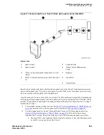
If there is no extended demarcation point, install the loopback jack directly at the network
interface point as shown in
Figure 107, Network Interface at Smart Jack, on page 361
.
2
If there is an extended demarcation point and the smart jack is not accessible, install the loopback
jack as shown in
Figure 108, Network Interface at Extended Demarcation Point (Smart Jack
3
If there is an extended demarcation point, but the smart jack is accessible, install the loopback
jack as shown in
Figure 109, Network Interface at Extended Demarcation Point (Smart Jack
Configurations without a Smart Jack
Install the loopback jack at the point where the cabling from the ICSU plugs into the “dumb” block. If
there is more than one “dumb” block, choose the one that is closest to the interface termination feed or the
fiber MUX. This provides maximum coverage for loopback jack tests. See
Figure 111, Network Interface at “Dumb” Block with repeater line to
Installation
To install the loopback jack:
1
Disconnect the RJ-48 (8-wide) connector (typically an H600-383 cable) at the appropriate
interface point and connect the loopback jack in series with the DS1 span. See
Network Interface at Smart Jack, on page 361
through
Figure 111, Network Interface at “Dumb”
Block with repeater line to Fiber MUX, on page 365
2
Plug the H600-383 cable from the ICSU into the female connector on the loopback jack.
3
Plug the male connector on the loopback jack cable into the network interface point.
NOTE:
Do not remove the loopback jack after installation. This is not a test tool and should
always be available to remotely test a DS1 span.
Содержание CMC1
Страница 1: ...Maintenance Procedures 555 245 103 Issue 1 1 December 2003 ...
Страница 14: ...Contents 14 Maintenance Procedures December 2003 ...
Страница 158: ...Server initialization recovery and resets System resets 158 Maintenance Procedures December 2003 ...
Страница 416: ...Additional maintenance procedures IP Telephones 416 Maintenance Procedures December 2003 ...
Страница 426: ...Index X 426 Maintenance Procedures December 2003 ...


