Packet and serial bus maintenance
G650 Serial Bus fault detection and isolation
Maintenance Procedures
271
December 2003
2
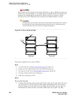
Determine if the Packet Bus fault is still present. If so, and if there are shorts on the Packet Bus,
perform Procedure 2 and/or Procedure 3 for only the circuit packs in those carriers that are
connected to the ‘‘shortened’’ Packet Bus. (Procedure 2 is performed for port circuit packs, and
Procedure 3 is performed for processor complex circuit packs.)
3
If the Packet Bus fault is not present, extend the Packet Bus to another carrier, and repeat the
procedure in the previous step. When a carrier that causes the fault to recur is added, and if there
are shorts, perform Procedure 2 and/or Procedure 3 for only the circuit packs in that carrier.
4
If the Packet Bus fault recurs as the Packet Bus is extended, and if Procedures 2 and 3 (if
performed) do not resolve the problem, the added carrier(s) that caused the problem to recur are
defective and must be replaced.
Other Port Networks
1
Terminate the Packet Bus so that it extends only from the carrier that contains the Active
Expansion Interface to the nearest carrier that contains the Maintenance/Test circuit pack. Place
the Maintenance/Test circuit pack into a carrier that contains an Expansion Interface circuit pack
in order to allow the procedure to isolate the failure to the smallest possible number of carriers.
2
Determine if the Packet Bus fault is still present. If so, and if there are shorts on the Packet Bus,
perform Procedure 2 and/or Procedure 3 for only the circuit packs in those carriers that are
connected to the ‘‘shortened’’ Packet Bus.
3
If the Packet Bus fault is not present, extend the Packet Bus to another carrier, and repeat the
procedure in the previous step. When a carrier that causes the fault to recur is added, and if there
are shorts, perform Procedure 2 and/or Procedure 3 for only the circuit packs in that carrier.
4
If the packet bus fault recurs as the packet bus is extended, and if Procedures 2 and 3 (if
performed) do not resolve the problem, the added carrier(s) that caused the problem to recur are
defective and must be replaced.
G650 Serial Bus fault detection and isolation
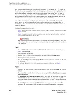
Each port network of G650s has a Serial Bus that allows the IPSI-2 (TN2312BP) to talk to the 655A
power supplies. This Serial Bus uses 2 previously-unused leads in the Universal Port Slot:
•
SPARE3 (pin 055) is I2C_SDA (Serial Data).
•
SPARE4 (pin 155) is I2C_SCL (Serial Clock).
Older TDM/LAN cables did not have these 2 leads, so the G650 required a new TDM/LAN cable. These
2 leads are not terminated on the TDM/LAN terminators (AHF110). This is an open-collector bus where
each power supply and each IPSI-2 provide a pull-up resistor to +5VDC for each of the 2 Serial Bus
leads. The bus has logic pulses extending between 0V and 5V. One of the IPSI-2s acts as master of the
Serial Bus and polls each of the power supplies based on their board address, which is derived from 4
board address leads in the power slot of the backplane. The G650 carrier addressing paddle card sets 3 of
these 4 address leads for the power slot.
Содержание CMC1
Страница 1: ...Maintenance Procedures 555 245 103 Issue 1 1 December 2003 ...
Страница 14: ...Contents 14 Maintenance Procedures December 2003 ...
Страница 158: ...Server initialization recovery and resets System resets 158 Maintenance Procedures December 2003 ...
Страница 416: ...Additional maintenance procedures IP Telephones 416 Maintenance Procedures December 2003 ...
Страница 426: ...Index X 426 Maintenance Procedures December 2003 ...


