


PARTNER Version Installation Manual
Page 74
- Issue 1c (09 April 2010)
IP Office Essential Edition
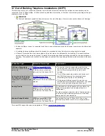
5.8 Using the External Output Port
All the IP Office control units are equipped with a EXT O/P port. The port is marked as EXT O/P and is located on the back
of the control unit adjacent to the power supply input socket.
The port can be used to control up to two external devices such as door entry relay switches. The usual application for
these switches is to activate relays on door entry systems. However, as long as the criteria for maximum current, voltage
and if necessary protection are met, the switches can be used for other applications.
The switches can be switched closed, open or pulsed (closed for 5 seconds and then open). This can be done in a number
of ways:
·
Using IP Office short codes.
·
Through the Door tab in Phone Manager Pro.
·
Through the Door Release option in IP Office SoftConsole.
·
Via the Open Door action in Voicemail Pro.
Default Short Codes
The following are the default short codes in the IP Office configuration for external output switch operation. They use the
short code features Relay On (closed), Relay Off (open) and Relay Pulse.
State
Switch 1
Switch 2
Closed
*39
*42
Open
*40
*43
Pulse
*41
*44
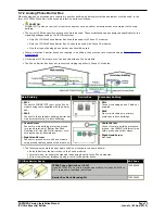
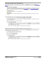
5.8.1 Port Connection
These ports are found on the rear of all IP Office control units. They are used for connection to external switching relays.
The port uses a standard 3.5mm stereo jack plug for connection.
The IP Office is able to open (high resistance), close (low resistance) or pulse (close for 5 seconds and then open) two
switches within the port. Either switch can be operated separately. These switches are intended for activation of external
relays in systems such as door opening systems.
·
CAUTION: In installations where this port is connected to a device external to the building, connection must be via a
towerMAX SCL/8 Surge Protector and a protective ground connection must be provided on the IP Office control unit.
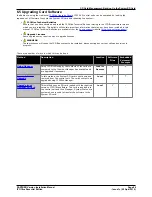
EXT O/P
Pin
Description
1
Switch 1.
2
Switch 2.
3
0 Volts (Ground/Chassis)
·
Switching Capacity: 0.7A.
·
Maximum Voltage: 55V d.c.
·
On state resistance: 0.7 ohms.
·
Short circuit current: 1A.
·
Reverse circuit current capacity: 1.4A.
·
Ensure that pins 1 and 2 are always at a positive voltage with respect to pin 3.
3.5mm stereo audio jack plugs are frequently sold as pre-wired sealed modules. It may be necessary to use a multi-meter
to determine the wiring connections from an available plug. Typically 3 (common to both relays) is the cable screen.
Содержание 1408
Страница 1: ... Issue 1c 09 April 2010 PARTNER Version Installation Manual IP Office Essential Edition ...
Страница 6: ......
Страница 58: ......
Страница 76: ......
Страница 94: ......
Страница 134: ......
Страница 140: ......
Страница 143: ...PARTNER Version Installation Manual Page 143 Issue 1c 09 April 2010 IP Office Essential Edition ...


