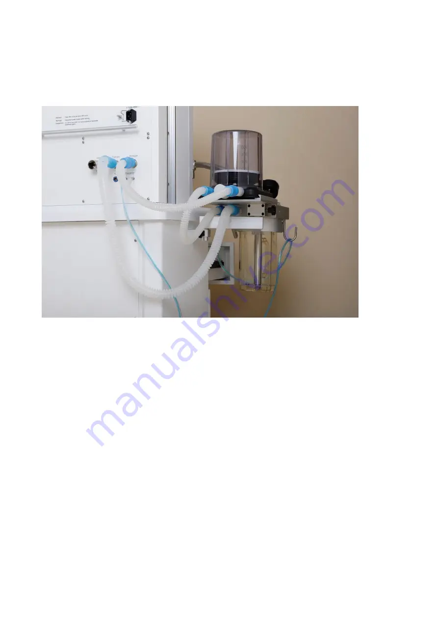
3.9 Connect the pipeline
Connect the pipeline among CO2 circle absorber, bellow and the body of anesthesia
machine.
Страница 1: ......
Страница 2: ...t specifications Liability of manufacturer The Company is only responsible for the safety reliability and performance of the equipment in the following circumstances Assembly operation expansion re ad...
Страница 3: ...sensors and oxygen sensors Do not store locate electrical wires on any part of this system If the following condition occurs the company is not responsible for the safety reliability of this system T...
Страница 4: ...ers are non legible return will not be accepted Please mark the model name and serial number at the same time give the reason for the return When this system is shipped back for maintenance users shou...
Страница 5: ...Intended use 177 2 1 2 Product performance structures 177 2 2 Appearance 177 2 3 Anesthesia Ventilator 212 2 4 Battery 212 2 4 1 Battery indicator 223 2 4 2 Installing Replacing Batteries 223 Chapter...
Страница 6: ...test 32 4 7 4 Continuous Pressure High alarm test 33 4 7 5 PRESSURE LOW alarm test 33 4 8 Preoperative preparations 33 Chapter 5 Basic Operation 34 5 1 Powering On the System 34 5 2 Standby Mode 34 5...
Страница 7: ...ume Control PRVC 41 6 5 3 1 Description 41 6 5 3 2 Start PRVC Mode 42 6 5 3 3 Parameter Setup Area in PRVC Mode 42 6 5 3 4 Set Parameters in PRVC Mode42 6 5 4 Pressure Support Ventilation PSV 42 6 5 4...
Страница 8: ...tting System Time 57 6 7 8 Calibration58 6 7 8 1 Pressure Sensor Zero Calibration 58 6 7 8 2 Flow Sensor Zero Calibration 58 6 7 8 3 O2 Cell Calibration 59 6 7 9 Service Modes Menu 59 Chapter 7 Operat...
Страница 9: ...Indicators 65 8 5 Silence Alarms 65 8 6 Alarm message 65 Chapter 9 Cleaning and disinfection 68 9 1 Clean and Disinfect the Anesthetic Machine housing 68 9 2 Disassembling the breath system 69 9 2 1 R...
Страница 10: ...on 74 10 5 1 21 O2 Calibration 74 10 5 2 100 O2 calibration 75 10 6 Touchscreen Calibration 75 10 7 Fault Diagnosis and Troubleshooting 75 Chapter 11 Accessories 77 A Product Specifications 78 A 1 Saf...
Страница 11: ...he device should have the power cable grounded to protect the main power supply outlet If the event of any abnormal situation Anesthetics workstation should be checked immediately Do not attempt to se...
Страница 12: ...be placed in the Anesthetics workstation for easy observation Class I special waste Depleted batteries must be replaced and disposed of in accordance with local regulations Class II special waste The...
Страница 13: ...ng USB interface Inspiratory flow Expiratory flow Bag position manual ventilation Mechanical ventilation Lock Unlock Flow control O2 Flush button Oxygen Sensor connector Bi directional rotation Spare...
Страница 14: ...not roll upward Temperature Limitation Class I special waste Depleted of used batteries must be in accordance with local regulations concerning the replacement and discarded Class II special waste The...
Страница 15: ...idal Enflurane EtHAL End tidal Halothane EtDES End tidal Desflurane EtSEV End tidal Sevoflurane EtISO End tidal Isoflurane EtN2O End tidal Nitrous oxide EtCO2 End tidal carbon dioxide Esens Expiratory...
Страница 16: ...Pmin Minimum pressure PCV pressure control ventilation PRVC pressure guaranteed ventilation volume control ventilation Pause Inspiratory pause time Psens Pressure Trigger Sensibility PSV Pressure sup...
Страница 17: ...gas scavenging systems ISO 80601 2 13 3 Anesthetics vapor delivery devices ISO 80601 2 13 4 Oxygen monitors ISO 80601 2 55 5 Carbon dioxide monitors ISO 80601 2 55 6 Exhaled volume monitors ISO80601...
Страница 18: ...de stream CO2 module IRMA CO2 AX module SpO2 module Auxiliary Common Gas Outlet ACGO Anesthetics vapor delivery device Anesthetics gas scavenging systems AGSS Auxiliary Oxygen Suction regulator Driver...
Страница 19: ...t absolute contraindications Warning This Anesthetics machine is intended for use by qualified Anesthetics personnel only or under their guidance Anyone unauthorized or untrained must not perform any...
Страница 20: ...ting bar 3 Anesthesia Ventilator 4 Handle 5 Drawers 6 Castors 7 ACGO switch When ACGO switch is on Fresh gas will be delivered to half open breathing system through ACGO outlet When ACGO switch is off...
Страница 21: ...he regulated pressure value of reserve cylinder gas 14 Fresh gas flowmeter Fresh gas flow control knob Turn flow control counterclockwise to increase gas flow Turn flow control Clockwise to decrease t...
Страница 22: ...1 Auxiliary electrical outlets 3 outlets on back 2 Fuse 3 Mains inlet 4 AGSS connection 5 Fresh Gas outlet 6 Driving gas 7 Flow sensor connector...
Страница 23: ...e of electricity failure Battery life is dependent on frequency of use For a properly maintained and stored Nickel hydrogen battery its life expectancy is approximately 2 years For more aggressive use...
Страница 24: ...tery is normal and need focus on battery status Indicates low battery and the batteries need to be charged Indicates too low battery and the batteries need to be charged immediately The capacity of th...
Страница 25: ...machine 2 Install the battery to the battery compartment as shown in the figure above 3 Install the battery cover Replacing batteries Replace batteries with reference to installing batteries...
Страница 26: ...ey are used near high frequency electrosurgical equipment This equipment must be installed by the company authorized engineer This Anesthetic machine has waste gas exhaust ports The operator of the ma...
Страница 27: ...stall the breath circuit Caution When installing the breathing tube hold the tube connector at both ends of the tube to prevent damage of the tube 1 The two breathing hoses are connected to the breath...
Страница 28: ...e Please refer to the user manual of Anesthesia Vaporizer 3 7 Power connector Warning Powering additional devices through the auxiliary power outlets can increase the total leakage current Test for le...
Страница 29: ...3 9 Connect the pipeline Connect the pipeline among CO2 circle absorber bellow and the body of anesthesia machine...
Страница 30: ...on of each component If the system fails a test do not use the device Contact a maintenance engineer 4 2 System Check Warning Ensure that the Anesthetic machine is not imbalanced and does not tilt mor...
Страница 31: ...se minimum flow Then turn the N2O flow control counterclockwise and set the N2O flow control to the rates shown in the table The O2 flow must meet the requirement listed in the following table Step N2...
Страница 32: ...system switch to the position 3 Set the O2 flow to 6L min 4 Make sure that the O2 flow stays constant 5 Set a vaporizer concentration of 1 Check that the O2 flow does not decrease more than 1 L min t...
Страница 33: ...dby screen after approximately 15 seconds c Audio and visual alarm indicators are triggered 4 7 1 Prepare for Alarm Test 1 Connect a test lung or manual bag to the Y piece patient connector 2 Set the...
Страница 34: ...nuous pressure high alarm is triggered 4 7 5 PRESSURE LOW Alarm Test 1 Set the bag Vent switch to vent 2 Set the Paw low alarm limit to 5 cmH2O 3 Disconnect the test lung from the Y piece patient conn...
Страница 35: ...s to minimum 9 Check that the breathing system is not damaged and correctly connected Warning Before connecting a patient flush the Anesthetic machine with 5 L min of O2 for at least one minute This r...
Страница 36: ...he System Off When a clinical procedure is completed 1 Check that the vaporizer is in the OFF position and all gas flow controls are set to off 2 Turn the system switch to the OFF position 5 4 Using t...
Страница 37: ...nsor or the O2 sensor is depleted the oxygen monitor can be set to OFF to prevent the occurrence of an O2 sensor alarm 1 Select System Settings O2 2 Set the oxygen monitor to ON or OFF 5 5 6 Set patie...
Страница 38: ...The display shows the start up screen and a start up music is given at the same time then enter the standby screen 6 3 Patient Setup 6 3 1 Select patient type Patient type can only be changed when th...
Страница 39: ...ume Control Ventilation VCV 6 5 1 1 Description Volume control ventilation referred to as VCV mode is a basic fully mechanical ventilation mode In the VCV mode ventilator delivers the preset tidal vol...
Страница 40: ...VCV in the Modes menu then the controls menu for VCV mode is opened 3 Adjust appropriately parameter settings for the patient and then confirm the settings so as to start VCV mode 6 5 1 3 Parameter S...
Страница 41: ...t the preset pressure throughout the preset inspiratory time at the preset respiratory rate During the inspiratory time the pressure is constant and the flow is decelerating The peak pressure Peak is...
Страница 42: ...de is opened 3 Adjust appropriately parameter settings for the patient and then confirm the settings so as to start PCV mode 6 5 2 3 Parameter Setup Area in PCV Mode When PCV mode is confirmed Key par...
Страница 43: ...the next breath For the following breath this pressure is constant during the set inspiratory time and the flow is decelerating The set tidal volume is achieved by automatic breath by breath regulati...
Страница 44: ...rameters is automatically switched over to the parameter setup area in this mode It is convenient to monitor and set The following figure shows these parameters to be set in PRVC mode FIGURE 6 9 Key p...
Страница 45: ...ssure provided by the ventilator is constant the flow will decrease until the inspiratory cycle off is reached when the expiration starts If no breath is detected within the interval determined by the...
Страница 46: ...4 FIGURE 6 13 All parameters in PSV mode 6 5 4 5 Set Backup Mode There are two different Backup modes relevant parameters are shown in a kind of different color 1 push Backup mode button select VCV o...
Страница 47: ...val Ts which is reserved for spontaneous breathing throughout the remainder of the breath cycle At the end of an SIMV breath cycle the cycle repeats If a PIM is not delivered the ventilator delivers a...
Страница 48: ...n SIMV PC mode FIGURE 6 16 Key parameters in SIMV PC mode 1 Pinsp Pressure control level above PEEP 2 Ti Inspiratory time 3 Rate Breath rate 4 Psupp Pressure support level above PEEP 5 PEEP Positive e...
Страница 49: ...pressure 6 Psens or Fsens Pressure trigger sensitivity or flow trigger sensitivity 6 5 5 4 Set Parameters in SIMV Mode The same method as 4 5 1 4 Figure 6 18 All parameters in SIMV VC mode Figure 6 19...
Страница 50: ...topwatch will start to count 2 The Stop the stopwatch by pressing the stopwatch button again and the button will change from green to grey and the stopwatch will stop counting 3 Reset the stopwatch by...
Страница 51: ...by status The patient data can be defined When the patient height and type have been defined the ventilator settings of tidal volume minute volume and respiration rate will change in accordance with t...
Страница 52: ...utton to open the loop selection menu Volume Flow loop or Pressure Flow loop can be selected Push button to open the waveform selection menu flow waveform volume waveform Pleth waveform optional or CO...
Страница 53: ...g Monitoring button the monitoring menu appears All monitoring parameters are displayed in this menu two sub menus are displayed Ventilation parameters in values 1 sub menu CO2 parameters and SpO2 par...
Страница 54: ...urning the control knob and press control knob or button to confirm The setting will not change before entering is pressed on the control knob or button is pressed again For high and low alarm limits...
Страница 55: ...2 only if O2 sensor is installed Apnea time 6 7 6 2 Alarm limits 2 The ventilation alarm settings can be accessed in the limits 2 sub menu The following figure shows limits 2 sub menu in the alarm men...
Страница 56: ...the alarm log If the alarm log is full the oldest alarm record will be overwritten The following figure shows alarm log sub menu Figure 6 28 Alarm log sub menu 6 7 7 System Menu When pressing System b...
Страница 57: ...nformation menu 6 7 7 2 Setup Menu The following settings can be accessed in this menu Loudness Language Units Sensor on off Figure 6 30 Setup Menu 6 7 7 2 1 Set Alarm Loudness Adjust the alarm loudne...
Страница 58: ...fect immediately Repeat for any other desired parameters 3 Press Exit button to return setup menu Figure 6 31 Units menu 6 7 7 2 4 Sensor on off When O2 sensor CO2 module or SpO2 module are installed...
Страница 59: ...ctions displayed disconnect the breathing circuit at the patient side of the flow sensor touch Start button 3 When calibration is complete verify that the message bar displays Calibration Completed 6...
Страница 60: ...Follow the instructions displayed disconnect the O2 sensor from breathing circuit touch 100 button or 21 button respectively 3 When calibration is complete verify that the message bar displays Calibra...
Страница 61: ...1 Check each gas supply connection and pressure 2 Gas flow values are shown on the respective flow meter 3 The O2 and N2O flow controls are linked a Increase the N2O flow The O2 control will increase...
Страница 62: ...ry Time 1 Select the TI hotkey 2 Press the control knob turn the knob to set TI is set to an appropriate values 3 Press the control knob to confirm and activate the change 7 3 4 Set Inspiratory Expira...
Страница 63: ...a no breath conditions is set as follows 1 Select Alarm Apnea time 2 Turn the control knob to set the Apnea time to the desired value 3 Press the button to confirm and activate the change 4 Closing th...
Страница 64: ...ate the oxygen sensor if the inaccuracies are large 7 5 2 Pressure Monitoring Pressure related parameters are measured as shown below PEEP Ppeak Pplat Pmean 7 5 3 Tidal Volume Monitoring Caution The t...
Страница 65: ...gered by a vital sign that appears abnormal or by a technical condition within the Anesthetic machine Alarms are indicated to the user by visual and audible alarm indicators 8 2 Alarms The anesthesia...
Страница 66: ...he level for all alarms are preset before the ventilator leaves the factory and cannot be changed 8 4 Alarm Indicators The anesthesia ventilator provides the following alarm indicators An alarm LED lo...
Страница 67: ...s If the problem persists contact your service personnel information Alarm conditions Alarm level Apnea No breath has been detected within the set apnea time High priority MVexp high Minute volume is...
Страница 68: ...ng tube obstruction EtCO2 three consecutive cycles detected sampling tube obstruction Medium priority SpO2 sensor disconnected SpO2 sensor disconnected Low priority Standby Return to standby mode High...
Страница 69: ...se normal system use Caution Clean and disinfect the equipment as required before it is put into use for the first time To help prevent damage refer to the manufacturer s data if you have questions ab...
Страница 70: ...te when the filter is discarded 9 2 4 Remove the Bag Arm 1 Loosen the locking nut counterclockwise 2 Remove the bag arm from the CO2 Circle Absorber 9 2 5 Remove the bellows Assembly 1 take away the s...
Страница 71: ...methods are different for different parts You need to select the appropriate method to clean and disinfect the parts based on the actual situations to avoid cross contamination This table is our recom...
Страница 72: ...Bag Arm First flush with water then soak it in solution mixed by water and detergent 30 minutes the suggested temperature is 30 41 after that treat by clean water finally wipe by using 70 medical use...
Страница 73: ...that all components of flow sensor are fully dry 2 Connect Flow sensor and inspiratory connector or expiratory connector Insert the inspiratory connector or expiratory connector into flow sensor and t...
Страница 74: ...ease leakage currents Check the total leakage current every six months All repairs servicing and the replacement of components must be undertaken by a trained engineer After repair carry out a pre use...
Страница 75: ...arts for damage Replace repair as necessary As necessary Install new cylinder gaskets on cylinder yokes Empty the water collection cup If there is water build up in it Empty and clean the overflow tra...
Страница 76: ...ation Part The O2 calibration is not required if no O2 sensor is configured or used Check that the oxygen sensor cables are connected correctly With ACGO port to calibrate remember turn off ACGO after...
Страница 77: ...ion Oxygen Cell Calibration 100 5 Make sure that the patient or test lung is disconnected from the system 6 Follow the prompts Before O2 100 calibration requests supply 10L min of O2 10 6 Touchscreen...
Страница 78: ...annot be closed Contact a service engineer Manual breathing airway pressure is too high APL valve is set too high Reset the APL valve Power indicator is not lit Power cord is not connected System and...
Страница 79: ...the biocompatibility requirement of ISO10993 1 to prevent any adverse reactions arising from such contact Disposal of the accessories shall comply with the applicable waste control regulations Gas Sup...
Страница 80: ...arthing equipment or protective ground conductor generates doubt the device must be replaced by Internal power supply battery Applied part Type B Breathing tubes Operating Mode Continuous Explosion Pr...
Страница 81: ...to 10 L min 0 to 15L min Accuracy 5 of full range A 4 Power Specifications Parameter Specification External AC power Input Voltage 100 240V Input Frequency 50 60Hz Input Power 150 VA System leakage cu...
Страница 82: ...0601 1 8 standards Control Knobs 1 Support clockwise counterclockwise rotation and pressing operation Button 4 Alarm pause alarm reset standby back to the main screen Interface Power supply An AC powe...
Страница 83: ...volume Range 50 1500ml optional 10 1500ml Increment 10 100 mL 5mL 100 1500 mL 10mL Respiratory rate Range 1 100 bpm increment 1 bpm Inspiratory time Range 0 1 10 0 s increments 0 1 s Respiratory ratio...
Страница 84: ...e 0 100 cmH2O Resolution 1 cmH2O Error of 2 4 of full scale actual reading Mean airway pressure Range 0 100 cmH2O Resolution 1 cmH2O Error of 2 4 of full scale actual reading PEEP Range 0 100 cmH2O Re...
Страница 85: ...n increments of 1 s Drive gas failure alarm Drive gas pressure is less than 280 kPa AC power failure alarm The mains breaks down or the power cord disconnects Low battery alarm Alarm battery time is 2...
Страница 86: ...n is intended for use in the electromagnetic environment specified below The customer or the user of ANESTHETIC MACHINE should assure that it is used in such an environment Emission test Compliance El...
Страница 87: ...ic Workstation requires continued operation during power mains interruptions it is recommended that Anesthetic Workstation be powered from an uninterruptible power supply or a battery Power frequency...
Страница 88: ...ed separation distance for transmitters in these frequency ranges c Field strengths from fixed transmitters such as base stations for radio cellular cordless telephones and land mobile radios amateur...
Страница 89: ...d 800 MHz the separation distance for the higher frequency range applies NOTE 2 The ISM industrial scientific and medical bands between 150 kHz and 80 MHz are 6 765 MHz to 6 795 MHz 13 553 MHz to 13 5...
Страница 90: ......
Страница 91: ......