7
4.2 Principle of hydraulic and electrical installation.
4.2.1 Case of a POOLeasy pH connected to a permanent power supply and filtration detection with a salt
chlorinator cell.
Description of callouts on Figure 3
A-
POOLeasy pH
B-
2-in-1 sensor holder placed on the main pipe prior to any salt chlorinator cell (H) or after all pool
accessories (heating, etc.). This injector sensor holder is the support for the measurement
electrode and injection valve.
C-
Treatment reagent tank
D-
Electrical cabinet for control of pool circulation pump
E-
Pool water circulation pump.
F-
Pool
G-
Pool filter
H-
Salt chlorinator cell
I-
Electrical cable connecting the instrument to the electrical box
Fig. 3
i
Содержание POOLeasy pH
Страница 1: ...INSTRUCTIONS AND USER MANUAL POOLeasy pH POOLeasy Rx Power at the service of water...
Страница 14: ...11 STEP 5 Place the probe holder B by inserting the injection tube in the direction of the waterflow 1 2 3 Q...
Страница 15: ...12 STEP 6 Securization on the pipe 1 50 pipe 2 63 pipe K C L K C L O...
Страница 16: ...13 Vertical...
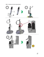
Страница 20: ...17 STEP 10 Installation of the short probe 80mm G J 1 2 3...
Страница 29: ...26 7 3 2 Installation of a long probe 120mm J G P 1 2 3...


