


Page 49
IronHorse GSD8 DC Drives User Manual – 1st Ed. Rev. A – 10/15/2019
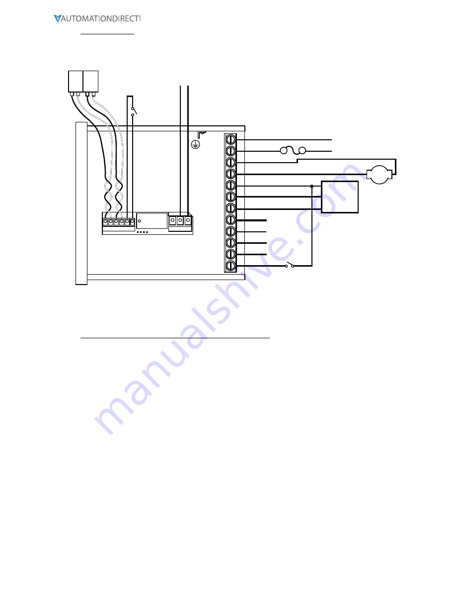
Wiring Diagram
P1-1
P1-2
P1-3
P1-4
P1-5
P1-6
P1-7
P1-8
GSD8-240-5C-D w/GSDA-AI-A8
GSD8-240-10C-D w/GSDA-AI-A8
GSD8-240-10N4X-A
*FUSE
MOTOR
P1-9
P1-10
P1-11
P1-12
* Size fuse according to unit and application. See
electrical specifications for maximums.
A+
COM
+5V
S1
S2
NO
C
NC
IN1
N
L
A-
}
AC Line Input 85-265VAC, 50-60 Hz
NOT USED
GND
+V
SIGNAL OUT
FLOW TRANSDUCER
(Frequency Output)
NOT USED
}
“FAULT”
CONTACT
INHIBIT
}
“Run”
Contact
Auto / Manual
Switch
SCADA SYSTEM
(Has built in
Excitation Supply)
NO C
P3
P6
1 2 3 4 5 6
+
-
+
-
1
2
3
+
-
+
-
4-20
OUT
4-20
IN
Relevant Math and Various Settings for this Application:
In this example, the pump turns 9.5 “shaft rotations” per liter. The maximum desired flow rate is 150.0
LPM, and the motor drives the pump at a 1:1 ratio, such that the motor speed at 150.0 LPM will be 9.5 x
150.0, or 1,425 RPM. Set parameter 31, S1 Reference RPM to 1425.
Set Parameter 30, Display Reference to 1500, which is the maximum flow rate (150.0 LPM, minus the
decimal point) when the motor is running at the Reference speed of 1,425 RPM.
The Flow Transducer has a pulse output rate of 73 pulses per liter. Set Parameter 32, S1 Pulses Per
Revolution to 73. The controller is “thinking” in LITERS per minute, but “controlling” the motor in
REVOLUTIONS per minute.
The Accel and Decel rates are expressed in “Display Units” (Engineering Units) per second, so we have
to divide our desired accel and decel rates by 60. Set Parameter 23, Accel Setting, to 17 (1000 / 60 and
rounded up), and set Parameter 24, Decel Setting, to 8 (500 / 60).
The settings for the “Fault” conditions are used to control the Alarm1 relay. The application requires
that a “Fault” condition is “true” (active) when Actual Speed is Outside Limits, or Target Speed is
Outside Limits, or waste flow has stopped (Main Pickup (Flowmeter) Stalled), or the GSD8 drive is at
Max. Output, or the 4-20 mA Input loop appears “broken”. Set Parameter 50, Alarm1 OR Activation
Conditions, to a value of 2 + 4 + 16 + 512, which equals 534. Set Parameter 65, Alarm1 OR Activation
Conditions, to a value of 2.
Conversely, we do NOT want “Fault” output to activate if any of the following conditions are true:
Target speed (either through the 4-20 mA input or the “front panel”) is set to zero, or an accel/decel
ramp is in progress, or an “Inhibit” input is active (UIN1 will be set for use as an Inhibit input).


