


Page 43
IronHorse GSD8 DC Drives User Manual – 1st Ed. Rev. A – 10/15/2019
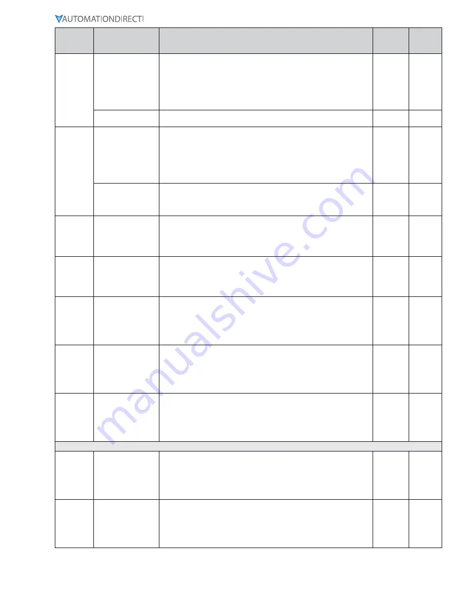
Parameter Parameter Name
Description
GSD8-
240-5C
All other
GSD8
drives
57
Alarm 1 Lower Limit
This setting defines either the lower limit, the lower end of a range for
the alarm region or a stall timeout. Alarm limits are set in display units
without regard to decimal point or colon position.
In Rate and Follower Modes, a limit of 123 could represent a display
value of 123, 12.3, 1.23, or 0.123. When in Time Mode, a limit of 123
would represent 1:23 on the display. When the lower limit is being used
to set a stall timeout for parameter 50 mode 7, the setting is in seconds.
Alarm 1 Pulse “OFF”
Time
This Parameter defines the number of seconds the output should be
disabled during the ‘off’ phase of an active pulsing alarm’s output.
58
Alarm 1 Upper Limit
This setting defines either the upper limit, the upper end of a range for
the alarm region or a stop timeout. Alarm limits are set in display units
without regard to decimal point or colon position.
In Rate and Follower Modes, a limit of 123 could represent a display
value of 123, 12.3, 1.23, or 0.123. When in Time Mode, a limit of 123
would represent 1:23 on the display. When the upper limit is being used
to set a stop timeout for parameter 50 mode 7, the setting is in seconds.
Alarm 1 Pulse Count
This setting determines how many pulses are outputted when the
alarm is activated and is configured in the pulse output style. When 0
is entered, the unit will be set for continuous pulses while the alarm is
active.
59
Alarm 1 Lower Limit
This setting defines either the lower limit or the lower end of a range for
the alarm region. Alarm limits are set in engineering units without regard
to decimal point or colon position. In Rate and Follower Modes, a limit
of 123 could represent a display value of 123, 12.3, 1.23, or 0.123. When
in Time Mode, a limit of 123 would represent 1:23 on the display.
60
Alarm 1 Upper Limit
This setting defines either the upper limit or the upper end of a range for
the alarm region. Alarm limits are set in engineering units without regard
to decimal point or colon position. In Rate and Follower Modes, a limit
of 123 could represent a display value of 123, 12.3, 1.23, or 0.123. When
in Time Mode, a limit of 123 would represent 1:23 on the display.
65
Alarm 1 Logical “OR”
Activation Conditions
(Flags Table 2)
This Parameter, in conjunction with Parameters 66 & 67, defines which
conditions will result in the Alarm 1 output being activated. The function
is that of a Logical “OR”ing of the selected Drive Condition Flags Table
2. A setting of zero defeats this “OR” function entirely. Please see
the sections “Setting and Reading Softswitches” and “Setting Alarm
Conditions” for further details.
66
Alarm 1 Logical
Activation Condition
Inverters (Flags Table
2)
This Parameter, in conjunction with Parameters 65 & 67, defines which
conditions will result in the Alarm 1 output being activated. The function
allows selected Drive Condition Flags Table 2 to be “inverted” before
being presented to the “inputs” of the “AND” function (see Parameter
67). Please see the sections “Setting and Reading Softswitches” and
“Setting Alarm Conditions” for further details.
67
Alarm 1 Logical
“AND” Activation
Conditions (Flags
Table 2)
This Parameter, in conjunction with Parameters 65 & 66, defines which
conditions will result in the Alarm 1 output being activated. The function
is that of a Logical “AND”ing of the selected Drive Condition Flags
Table 2. A setting of zero defeats this “AND” function entirely. Please
see the sections “Setting and Reading Softswitches” and “Setting Alarm
Conditions” for further details.
Alarm Output #2 Setup Parameters
70
Alarm 2 Logical “OR”
Activation Conditions
(Flags Table 1)
This Parameter, in conjunction with Parameters 71 & 72, defines which
conditions will result in the Alarm 2 output being activated. The
function is that of a Logical “OR”ing of the selected Drive Condition
Flags. A setting of zero defeats this “OR” function entirely. Please see
the sections “Setting and Reading Softswitches” and “Setting Alarm
Conditions” for further details.
71
Alarm 2 Logical
Activation Condition
Inverters (Flags Table
1)
This Parameter, in conjunction with Parameters 70 & 72, defines which
conditions will result in the Alarm 2 output being activated. The function
allows selected Drive Condition Flags to be “inverted” before being
presented to the “inputs” of the “AND” function (see Parameter 72).
Please see the sections “Setting and Reading Softswitches” and “Setting
Alarm Conditions” for further details.


