background image

10

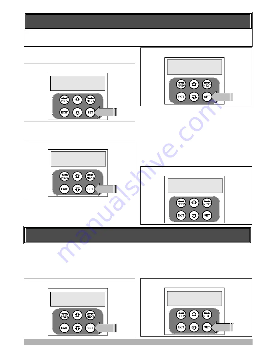
SETTING TIMED TRAVEL

STEP 1. NAVIGATING TO “TIMED TRAVEL MENU”

To navigate to the Menu 10.2 from the MAIN SCREEN simply
press PREV, SET then NEXT. Press SET to start the setup.

STEP 2. CONFIRMING READY TO START.

The CB-19 will prompt you to confirm that the motor wiring is
complete. Press SET to continue.

The controller will now prompt you to confirm that you under-
stand that

no current trip obstruction detection is available

when using timed travel. Press SET if you accept this.

STEP 3. SELECTING THE NUMBER OF MOTORS.

The controller will now prompt for the number of motors to be
entered. Use the UP or DOWN key to select the correct number
and then press SET.

STEP 4. SELECTING SETUP METHOD.

The controller will now prompt for the setup procedure to be
selected. Press SET to set the travel times by actually driving the
motor(s) or press EXIT to enter exact time parameters. Continue
with STEP 5 if “DRIVE MOTORS” is selected or go to STEP 5A
if “ENTER TIMES” is selected.

This section shows how to set the travel times when using drive units with slip clutches etc. Two methods are available for set-
ting up the travel times. The first allows the installer to drive the motor(s) so that the actual travel time can be recorded. The
second allows exact times to be entered.  Note: The limit setting procedure can be aborted at anytime by pressing EXIT.

MENU 

 10.2

Timed 

 Travel


PRESS 

Selecting Timed Travel Setup

Selecting Install Method


PRESS 

Confirming Obstruction Detection is Disabled

SET=Drive 

 Motors

EXIT=Enter 

 times

Current 

 Trips 


Are 

 DISABLED 

 OK?


PRESS 

Confirming Wiring Is Completed

Motor 

 Wiring

Completed?

STEP 5. ADJUSTING GATE LEAF SYNCHRONIZING
DELAYS. (Dual gate installations only)

For dual gate installations, the controller will prompt for you to
edit the gate leaf synchronizing delays. The settings are used to
introduce a delay between when the motors start so that overlap-
ping gates are opened and closed in the correct order. Press EXIT

to continue with STEP 6 or press SET to access the gate leaf syn-
chronizing delay parameters. See PARAMETER VIEW AND

EDIT for adjustement procedure. 

STEP 6. CONFIRMING GATE IS OPEN.

The controller will now prompt for you to comfirm that the gate
is open. If the gate is open press SET and continue with STEP 7.

SETTING TIMED TRAVEL - DRIVE MOTORS

Edit 

 Gate 

 Sync 


Delays?


PRESS 

Selecting to Edit Synchronizing Delay Times

Is 

 Gate 

 Open?


PRESS 

Confirming Gate is Open

Содержание CB-19

Страница 1: ...COPY Warning Failure to comply with the installation instructions and the safety warnings may result in serious personal injury and or property opener or controller damage Installation Instructions C...

Страница 2: ...GARAGE DOOR OPENERS GATE OPENERS REMOTE CONTROL ACCESS SOLUTIONS...

Страница 3: ...ING UP THE CONTROLLER 7 SETUP TRAVEL 7 LIMIT SWITCH AMP TRAVEL SETUP 9 RE PROFILING TRAVEL 10 SETTING TIMED TRAVEL 11 SETTING PEDESTRIAN POSITION 12 DESCRIPTION OF STANDARD OPERATION 13 CONTROL BOARD...

Страница 4: ...d for the installer to touch any console buttons during the coding process When all transmitters are coded a trans mitter storage report can be generated which can be easily transferred to a P C for r...

Страница 5: ...al 2 16 MOTOR 2 close limit switch input terminal 17 MOTOR 2 open limit switch input terminal 18 COM terminal for Terminals 16 17 19 20 19 MOTOR 1 close limit switch input terminal 20 MOTOR 1 open lim...

Страница 6: ...ansmitter Testing See Page 23 Event History Display See Page 23 Memory Usage See Page 23 Periodic Service Cycle Counter See Page 24 Parameter List 1 Open Lock Time 2 Close Lock Time 3 Pre Opn Lock Tim...

Страница 7: ...NG CONTROL SWITCH INPUTS When remote control operation is only required the CB 19 s con trol switch inputs are not utilised It is however strongly advised that a Photo electric Safety Beam be used to...

Страница 8: ...borted at anytime by pressing EXIT STEP 1 NAVIGATING TO LIMIT AMP TRAVEL MENU To navigate to the Menu 10 1 from the MAIN SCREEN simply press PREVto display MENU 10 followed by SET to display MENU 10 1...

Страница 9: ...console keypad or Button 1 and 4 of a transmitter After making adjustments to the limit switch positions always re approach the limit at full speed by driving the motor close a short distance and then...

Страница 10: ...lly close and open gate several times and learn the gates load and travel characteristics When the setup is complete the MAIN SCREEN will be displayed with the gate shown to be OPEN The Gate can now b...

Страница 11: ...g up the travel times The first allows the installer to drive the motor s so that the actual travel time can be recorded The second allows exact times to be entered Note The limit setting procedure ca...

Страница 12: ...me Save Settings PRESS Confirming Settings SETTING TIMED TRAVEL ENTER TIMES STEP 5A ENTERING TIMED TRAVEL PARAMETERS When the ENTER TIMES method is selected a list of parameters is provided to configu...

Страница 13: ...Activated by PED terminal with N O switch or by transmitter button with PED Function assigned The pedestrian access operation partly opens the gate to allow pedestrian access but prevent vehicle acce...

Страница 14: ...pplies 0 1 25 5 1 0 0 1 SEC 2 AMP TRIP LIMIT Motor drive electronics current limit 0 13 13 1 AMPS 2 PARAMETER AMP LIMITS MIN MAX DEFAULT STEP UNITS MENU MOTOR 1 OPEN LIMIT AMPS Sets Motor 1 open limit...

Страница 15: ...tions for safety reasons A P E beam must be used for these features to be activated AUTO CLOSE AFTER POWER UP Auto close after power up is normally not enabled for safety rea sons but can be enabled i...

Страница 16: ...configured to a SWIPE type input for pedestrian access This provides full functionality with the P E Triggered Pedestrian auto close function REMOTE CODE The controller supports the Remote Code Set fe...

Страница 17: ...input is used to alter the P E trig gered auto close feature so that P E triggered auto close is only initiated when the gateway is exited The direction of travel is determined by the sequence in whi...

Страница 18: ...yed Using the NEXT PREV buttons step through the list of parameters until the required parameter is displayed If the parameter s value is not to be changed then skip to step 7 when finished viewing th...

Страница 19: ...ode Transmitter menu will now be shown Press EXIT to return to the MAIN SCREEN and test the transmitter MENU 1 Code Transmitter PRESS Starting Code Transmitter Procedure Press Tx er Button LIST Press...

Страница 20: ...cheme which ties the store location to the transmitter s owner STEP 5 SELECTION OF ID OR SN DISPLAY When the cursor is moved to the ID SN indicator the UP and DOWN buttons toggle between displaying th...

Страница 21: ...tter s location within the list NOTE VIEW will not be shown if the transmitter is not stored 20 THE CONTROLLER PROVIDES A TRANSMITTER LISTING FACILITY WHICH ENABLES THE USER TO FIND A TRANSMITTER LOCA...

Страница 22: ...code operation is selected for a location that already contains a transmitter then the BASIC CODE TRANSMITTER PROCEDURE will be initiated and the new transmitter will replace the existing one Note tha...

Страница 23: ...for 2 seconds The example shows Button 1 being used but it could be any button It can even be an unused button on the existing transmitter STEP 5 CONFIRM TRANSMITTER BUTTON TO BE CODED Within 10 seco...

Страница 24: ...be displayed that shows the transmitter details along with the button pressed The example below shows the case when transmitter number 124 is activated by button 4 Note ID is selected for display MENU...

Страница 25: ...1234 When finished viewing simply press EXIT 24 Viewing Service Counter Service Counter CYCLES 60000 Viewing Counters 1 Open Cycles 1234 1 Open Cycles 2 Close Cycles 3 Ped Cycles 4 Warranty Cycles 5...

Страница 26: ...VAC 24VAC 30VDC 5AMPS RECEIVER TYPE UHF 433 92 MHz AM Receiver RECEIVER CODE STORAGE CAPACITY 30 x 4 Button Transmitter Codes TRANSMITTER FREQUENCY 433 92 MHz CODING TYPE Hopping Code No of CODE COMBI...

Страница 27: ...aims any liability of whatsoever nature in respect of any claim or demand loss or damage which arise out of a accidental damage to or normal wear and tear to the Product or to the Product s components...

Страница 28: ...GARAGE DOOR OPENERS GATE OPENERS REMOTE CONTROL ACCESS SOLUTIONS...

Отзывы: