background image


AUTO 

CRIB


d.


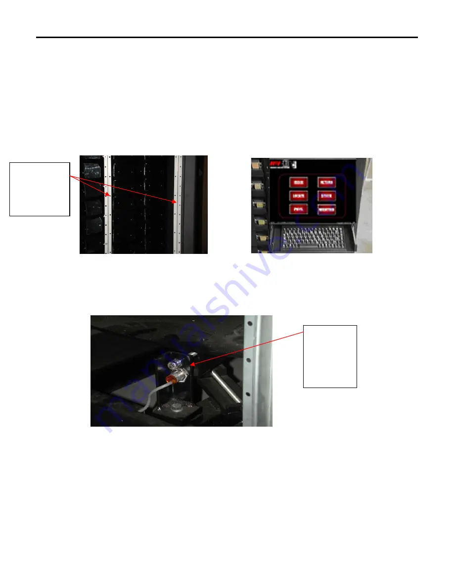
The Display Assembly fits below the power panel and above the return tray assembly. 

e.


Install the studs through the holes, attach, and tighten the 2 extended wing nuts and 2 
nylocks from the backside.  Install the extended wing nuts on the right of the computer 
(while looking at the back of the PC).  Install the nylocks on the left of the computer 
using a 3/8 open end wrench. 

f.


Attach the DB9 cable and AC plug to the outlets located on the bottom of the power 
panel. 

g.


Attach the Cat5 cable from the NIC card located at the top of the Display Assembly to 
the hub provided by AutoCrib, Inc. 


Mount display 
Studs In Z 
channel holes 
here. 


9.


Remove main platter locking bolt 
a.


Bolt is located on the sensor bracket below bin door #1. 


Remove bolt 
before using 
machine 
using the 2 – 
9/16 open end 
wrenches. 

b.


Loosen the lock nuts and unscrew the bolt using two 9/16 wrenches. 

c.


Retain the bolt and nuts for possible future use. 


Note: This bolt is inserted horizontally through the top of the bracket and into one of the radial arms on the main 
platter. Do NOT loosen the bracket-mounting bolt, which holds the bracket down on the frame. 
 

10.


Attach power and network services 
a.


Uncoil the power cord and route it through the bottom of the frame. 

b.


Attach power cord to a standard UPS (provided with the system) to a 120 VAC power 
outlet – (max usage 4 Amps). 


Содержание C

Страница 1: ...AUTO CRIB 16812 Gothard Street Huntington Beach CA 92647 Phone 714 274 0400 Fax 714 274 0399 RoboCrib Operations Manual Model C Last Revision 6 20 2003 1 ...

Страница 2: ...6 iii Restocking Using the Manual Method 17 iv Perform a Physical Count on One Bin 17 v Perform a Physical Count on All Bins 17 vi Issue an Item from the RoboCrib 17 vii Return an Item to the RoboCrib 17 viii Locate an Item in the RoboCrib or anywhere in the AutoCrib system 18 ix Troubleshooting Using the Maintain Function 18 Section IV Trouble Shooting Common Problems Install or Replace a Touch S...

Страница 3: ... 4 Used to install the leveling feet during installation o 1 3 8 Used to tighten the nyloc bolts on the RoboCrib PC Level Cordless Drill Used to uncrate the RoboCrib Socket Driver 7 16 Used to remove the bolts on the panels of the RoboCrib 2 Phillips Screwdriver Pin In Hex Screwdriver included Used to remove the security bolts on the panels of the RoboCrib Flat Head Screwdriver 3 ...

Страница 4: ... sure the forks of the forklift are inserted properly into the fork points on the frame Do not lift on the Main platter It is important that the feet of the forklift are completely inserted into the fork points b Unwrap the unit and roll the RoboCrib to its set up location c Return the pallet and straps to AutoCrib Inc for credit or store for future use II Installation 1 Locate the keys which are ...

Страница 5: ...Door cover panel Use the Pin In Hex driver to remove the screws Remove screws using the pin in hex screwdriver and 7 16 socket driver Remove these panels Keys to RoboCrib are connected to Z channel 7 Lift up on panels to disengage the tabs located on edges and pull out on the panel to remove it 8 Remove display assembly from box and prepare for the installation a Note the keypad drawer slides in a...

Страница 6: ...b provided by AutoCrib Inc Mount display Studs In Z channel holes here 9 Remove main platter locking bolt a Bolt is located on the sensor bracket below bin door 1 Remove bolt before using machine using the 2 9 16 open end wrenches b Loosen the lock nuts and unscrew the bolt using two 9 16 wrenches c Retain the bolt and nuts for possible future use Note This bolt is inserted horizontally through th...

Страница 7: ...r CCW position b As each Motor switch is actuated the appropriate platter should turn and the sensor lights should blink While testing each motor please note how the platters should react to the movement i Main Main Platter the entire internal array will rotate ii LSP Large Sub Platter 3 individual and 3 groups of 3 tray assemblies will rotate iii SS3 2 1 Small SubPlatters Individual tray assembli...

Страница 8: ...ed with the management station Use this form to begin the setup of the management station b Upon startup of the management station Carbon Copy and the Autocrib software will start c Exit the Autocrib software d Place the database file sent to you in the C Program Files Autocrib folder You may have received a zipped file This will require use of the WinZip software e Restart the Autocrib software f...

Страница 9: ... move the platter in the CW and CCW direction to ensure there is not an object impeding its movement 2 To reset the RoboCrib software type the supervisor password and restart the RoboCrib software 3 Allow the RoboCrib to recalibrate 4 If an error message appears again during the calibration call Autocrib Technical Support v Once the calibration sequence has been completed the RoboCrib software wil...

Страница 10: ...nt screws iii Types of Walls 1 Right Front and Left Rear corner panels 2 each 2 Right Rear and Left Front corner panels 2 each 3 Back Panels 2 each 4 Bin Door Panel 1 each 5 Return Bin 1 each 6 Vertical Z Channel 3 upright rack mount rails which holds the a Bin Door Assembly b Control Panel c Touchscreen Display Assembly 2 Platters a Main Platter MP i Large center platter ii 4 8 diameter iii Drive...

Страница 11: ...1 2 cond 18 AWG Stranded BW 2 Attached with 093 pin and socket connectors ii Signal 1 5 cond 22 AWG Shielded 2 Attached with HDE MTA 156 connectors III Posts Hex Shafts Mounting Arms and Tray Assemblies 1 Main Post a The large center support post with top and bottom mounting collars b Houses the wiring for the Large Sub Platter motor c Supports the three Large Sub Platter arms and the three Small ...

Страница 12: ...cted by a slide pot assembly that converts its absolute position into a signal which is sent to the controller This signal is used to position the baffle doors and calibrate at start up c The baffle assembly can be removed and replaced There are four screws on the vertical Z channels and on ribbon cable connection VI Wind Protection 1 Mechanical Wind Indicator The Wind Indicator is a bead on a spr...

Страница 13: ... one and two winds from zero iii Red The platter is greater than two winds from zero d The PIC chip will prevent the platter from moving any farther than 2 1 2 winds Therefore the system will not allow the platters to be moved manually or through the Maintain program greater than 2 1 2 winds 13 ...

Страница 14: ...3 Proper Loading Procedure a Before installing the RoboCrib use the test pies to select a proper bin size for the items b ITEMS MUST NOT PROTRUDE FROM BIN TRAY PERIMETERS Therefore if an item does not fit easily into the bin choose a larger bin size c Print the Reorder by RoboCrib report which is found in Standard Reports under the Purchasing Category d Create a purchase order and a tag for the Ro...

Страница 15: ...ound under Software Operations a Times when Maintenance Mode may be used are i Access items from the machine in an emergency or for testing purposes ii Rotate platters iii Open doors iv Perform other basic tasks without using the RoboCrib software v To ensure the machine is operating normally on initial installation of the machine vi To ensure a bin has been set up properly and has an item inside ...

Страница 16: ... problems or call bins II RoboCrib Software Operations NOTE An employee must be designated as a stocker in order to perform the following functions 1 Restocking Using the Automatic Bin Method a Press the Stock button b Enter your employee ID and PIN number c Press the Automatic button d Press the By Bin button e Type in the bin number or hold the bar coded label on the package in front of the lase...

Страница 17: ...the system will write the default 0 into the on hand and burn fields 5 Perform a Physical count on all bins a Print the RoboCrib physical count sheet from the Reports Inventory module b Press the Physical button c Enter you Master ID and PIN number d Press the All button and then wait for the machine to position to the first bin e When prompted move the bin door bypass switch to TEST f Physically ...

Страница 18: ...on a Press the Maintain button b Type in the your Employee ID and PIN You must have Supervisor level access indicated in your employee detail record in the AutoCrib software c To call a bin type FET BBB P B is for Bin Number P is for Baffle Position Ie FET 21 L 3 This will call bin 21L and set the baffle position for a fourth pie d Baffle Positions P are as follows i 1 twelfth pie ii 2 sixth pie i...

Страница 19: ...be contacted 2 System will not calibrate a The RoboCrib will automatically begin the calibration procedure when the RoboCrib software is started b If the machine is unable to calibrate the software will provide the user with an error message Please refer to Appendix II 3 The software will not initiate the Calibration Sequence a Check to make sure all of the doors are closed or set the bin door byp...

Страница 20: ...ide the door e Check the wiring connection f Make sure the other doors work g Replace a non functioning assembly with a known good assembly 7 Replacement of Controller a Remove the Right Front panel section so that the display and controller are accessible b Disconnect the door wiring motor wiring sensor wiring on top of controller the DB9 cable and the power cable from the PC c Remove the six scr...

Страница 21: ... place any liquid into the keyboard This may damage the internal working of the keyboard c AutoCrib suggests cleaner be applied to a rag before wiping the keyboard 4 Touch Screen a Wipe the screen with a clean soft rag b 409 or a glass cleaner can be used on the rag c Never spray directly on the touch screen membrane This could damage or short the membrane II Preventive Maintenance Hardware After ...

Страница 22: ...r mounts outward III Preventive Maintenance Hardware After 1 year and every year thereafter 1 Keep bin doors free of build up 2 Clean touchscreen DO NOT SPRAY DIRECTLY ON SCREEN 3 Check for dropped product on the Main platter 4 Check and adjust the tension on the chains 5 Lube dry lube only the chains sprockets door hinges latch assemblies and plastic bearings 22 ...

Страница 23: ...in to be fetched a LSP number b SSP number c Bin number on platter d Baffle position c calibration status 0 not calibrated since poweron 1 calibrated 2 encoder B error so internal position is wrong 3 platter reference mark not detected so wrap count may be wrong 4 platter reference mark was detected but was not within ref error limit 5 baffle pot voltage out of range w wrap count 0 or 1 d directio...

Страница 24: ...ealt with in a number of manual ways The development of the model C has a number of significant improvements in dealing with the above problems The first improvement is a rotational potentiometer has been mounted both on the LSP platter and the Main Platter These potentiometers are electromechanical devices that that have the ability to read out a specific voltage based on the number of rotations ...

Страница 25: ...wind count and attempt to recalibrate 3 times if unsuccessful system will lock touch screen and display error Encoder B not working on platter X See supervisor Notes Encoder B errors can be caused by a number of things The most common causes are follows 1 The drive chain on affected platter is too tight causing an oscillation on start up of the motor The paddle wheel on the back shaft of the motor...

Страница 26: ...otes A C4 error is caused by a condition where the machine has rotated more than 84 pulses past where it expected to see the Ref mark on the affected platter This can be caused by a missing Ref tab or more likely the use of the manual platter movement switches If a user moves the platter in a direction that would move it pass the ref tab and then the machine fetches a bin in the opposite direction...

Страница 27: ... error occurs normally when a motor is not functioning or disconnected or it s sensors encoders are not functioning and will occur at the beginning of the fetch cycle see diagram above The administrator should check the connections first Everything appears normal the next step would be to begin changing the components with a functioning platter to identify the problem part Time S1 Full speed part ...

Страница 28: ...or should remove the side panel of the machine and inspect the affect platter and chain for any possible obstructions If there are none the next step should be to attempt to move the platter with the manual switches If the machine will moves then proceed to the step 2 2 The other possible condition is the sensors encoder is not reporting the movement or pulses back to the controller This will caus...

Страница 29: ...l Ramp Ramp Notes An S3 error is usually a soft jam and is caused by an item that is pinched between the chain and a sprocket This almost always happens on the LSP or serpentine chain The administrator should remove the side panel and inspect the chain for any obstructions Clear any obstructions and restart the machine so it recalibrates Time S3 Full speed part Of move Check 2 Check 1 Fetch Begins...

Страница 30: ...eed Accel Decel Ramp Ramp Notes An S4 error indicates a hard jam This occurs when something stops the machine very quickly as opposed to just slowing it down in a soft jam condition The administrator should remove the side panel and inspect the machine for any obstructions Clear the obstructions restart the machine forcing a recalibration Time S4 Full speed part Of move Check 2 Check 1 Fetch Begin...

Страница 31: ...ing open during platter movement The system on detection will immediately stop the rotation of all platters as a safety hazard has occurred The user only needs to close the door The system will automatically refetch the called bin These conditions are normally caused by an incomplete latching of a door by the previous user Instruct the user to retrain the users on proper door closure Time S5 Full ...

Отзывы: