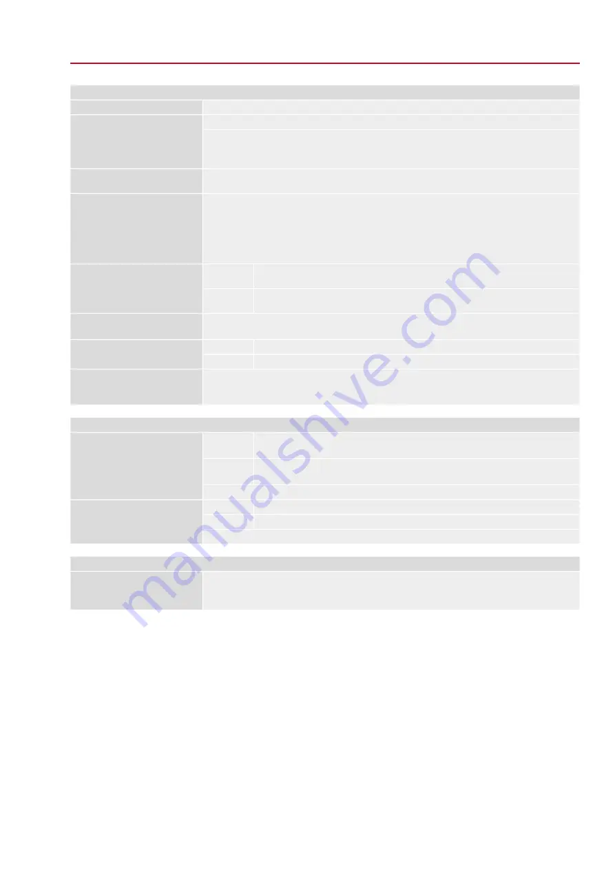
AUMA FQM Скачать руководство пользователя страница 33

Service conditions

Up to 100 % relative humidity across the entire permissible temperature range

Humidity

IP68

Enclosure protection according to
EN 60529

According to AUMA definition, enclosure protection IP68 meets the following requirements:

Depth of water: maximum 8 m head of water

Duration of continuous immersion in water: Max. 96 hours

Pollution degree 4 (when closed), pollution degree 2 (internal)

Pollution degree according to
IEC 60664-1

FQM 05.1/07.1 with valve attachment F07 = 0.3 g, 10 to 200 Hz
FQM 05.1/07.1 with valve attachment F10 = 0.5 g, 10 to 200 Hz
FQM 10.1/12.1 with valve attachment F10 = 0.3 g, 10 to 200 Hz
FQM 10.1/12.1 with valve attachment F12 = 0.5 g, 10 to 200 Hz
Resistant to vibration during start-up or for failures of the plant. However, a fatigue strength may not be
derived from this.

Vibration resistance according to
IEC 60068-2-6

KS: Suitable for use in areas with high salinity, almost permanent condensation, and high
pollution.

Standard:

Corrosion protection

KX: Suitable for use in areas with extremely high salinity, permanent condensation, and
high pollution.

Option:

Double layer powder coating
Two-component iron-mica combination

Coating

AUMA silver-grey (similar to RAL 7037)

Standard:

Colour

Available colours on request

Option:

500 fail safe operations (ESD cycles)
AUMA fail safe units meet or even exceed the lifetime requirements of EN 15714-2 in motor operation.
Detailed information can be provided on request.

Lifetime

Special features for use in potentially explosive atmospheres

II 2G Ex db eb IIB T4 Gb, or
II 2G Ex d IIB T4 Gb

ATEX:

Explosion protection

Ex db eb IIB T4 Gb, or
Ex d IIB T4 Gb

IECEx:

For exact version, refer to actuator name plate.

DEKRA 16 ATEX 0080 X

ATEX:

Certificates and standards

IECEx DEK 16.0039X

IECEx:

All standards applied and their respective issues are indicated on the certificates supplied.

Further information

ATEX Directive: (2014/34/EU)

Electromagnetic Compatibility (EMC): (2014/30/EU)

Machinery Directive: (2006/42/EC)

EU Directives

33

FQM 05.1 – FQM 12.1 / FQMEx 05.1 – FQMEx 12.1 

Technical data

Содержание FQM

Страница 1: ...Fail safe unit FQM 05 1 FQM 12 1 FQMEx 05 1 FQMEx 12 1 Assembly and commissioning Operation instructions...

Страница 2: ...mbly 12 4 1 Mounting position 13 4 2 Actuators for fail safe units 13 4 3 Fail safe unit mount to valve 13 4 3 1 Overview on coupling variants 13 4 3 1 1 Fail safe unit to valve mount 17 5 Electrical...

Страница 3: ...on 30 8 2 Indication lights of local controls 30 8 2 1 Indication lights indications modify 31 9 Signals output signals 31 9 1 Status signals via output contacts digital outputs 31 9 1 1 Assignment of...

Страница 4: ...he end user or contractor of the plant are responsible for respect and control of these regulations standards and laws Commissioning Prior to commissioning it is important to check that all settings m...

Страница 5: ...ise closing i e the driven shaft turns clockwise to close the valve 1 3 Warnings and notes The following warnings draw special attention to safety relevant procedures in these operation instructions e...

Страница 6: ...lowing a fail safe operation do NOT activate manual operation This means for all interventions the push button at the actuator handwheel must NOT be pressed prior to initialisation Information Success...

Страница 7: ...acturer 2 Address of manufacturer 3 Type designation 4 Order number 5 Actuator serial number 6 Nominal operating time in s for a part turn movement of 90 7 Max torque in direction OPEN CLOSE 8 Type of...

Страница 8: ...0 1 12 1 Ex marking Table 1 Marking for explosion protection with example 3 3 Not used Not used Protection type of electrical connection 3 Terminal compartment Ex e increased safety 4 Terminal compart...

Страница 9: ...order number or serial number Figure 5 Link to AUMA Assistant App For further Service Support Software Apps refer to www auma com 2 2 Short description In emergencies the fail safe unit is capable of...

Страница 10: ...wheel Check eyebolts for tight seat in housing verify reach of the screws Observe manufacturer specifications for fixing lifting straps and round slings Heed total weight of arrangement Figure 6 Examp...

Страница 11: ...trols may only be stored permanently down to 30 C On request actuators controls may be transported in specific cases and for short duration at temperatures down to 60 C Long term storage For long term...

Страница 12: ...d for transport For FQM 05 1 07 1 M10 thread for FQM 10 1 12 1 M12 thread We recommend glueing the screws using thread sealing material to avoid contact corrosion in the thread To compensate for vibra...

Страница 13: ...valve attachments according to EN ISO 5211 For rotating non rising valve stem 4 3 1 1 Fail safe unit to valve mount Unbored couplings or couplings with pilot bore must be machined to match the valve s...

Страница 14: ...ling Figure 10 Examples Fit coupling 1 Coupling 2 Valve shaft 3 Grub screw 4 Screw with washer Figure 11 Mounting positions for coupling Table 6 FQM 12 1 FQM 10 1 FQM 07 1 FQM 05 1 Dimensions mm F14 F...

Страница 15: ...Valve flange bore 1 Setting screw 2 View on valve flange and rotary movement of FQM when unfastening the setting screw For CCW version the FQM bores should overlap the bores of the valve flange rather...

Страница 16: ...ng torque Nm Threads Strength class A2 80 A4 80 10 M6 24 M8 48 M10 82 M12 200 M16 392 M20 Information If the bores are not yet aligned for dimension Tmin the mounting procedure must be aborted The fol...

Страница 17: ...ator actuator controls and fail safe unit the maximum power consumption of 360 W for the fail safe unit has to be accounted for In case separate power supply for the fail safe unit is provided 360 W h...

Страница 18: ...ment is designed in protection type Ex e increased safety The interior of the flameproof enclosure Ex d of connected housing remains closed when removing the cover 1 2 Insert cable glands suitable for...

Страница 19: ...tted In case of a fault Hazardous voltage while protective earth conductor is NOT connected Risk of electric shock Connect all protective earth conductors Connect PE connection to external protective...

Страница 20: ...if damaged 3 Apply a thin film of non acidic grease e g petroleum jelly to the O ring and insert it correctly 4 Fit cover 1 and fasten screws 2 evenly crosswise 5 Fasten cable glands and blanking plug...

Страница 21: ...e Failure to observe this warning results in death or serious injury Disconnect device from the mains before opening 1 Loosen screws 2 and remove cover 1 2 Loosen screws 4 and remove socket carrier 5...

Страница 22: ...earth conductor is NOT connected Risk of electric shock Connect all protective earth conductors Connect PE connection to external protective earth conductor of connecting cables Start running the devi...

Страница 23: ...ether O ring 3 is in good condition replace if damaged 4 Apply a thin film of non acidic grease e g petroleum jelly to the O ring and insert it correctly 5 Fit cover 1 and fasten screws 2 evenly cross...

Страница 24: ...tialisation Prerequisites for starting initialisation Power supply applied Actuator controls are ready for operation booted after power supply connection 24 V DC is applied at ESD input refer to wirin...

Страница 25: ...d stops of the fail safe unit exclusively limit the swing angle The swing angle set in the factory is indicated on the name plate of the fail safe unit Figure 22 Name plate example Exposed rotating pa...

Страница 26: ...nd position 2 Remove screw plug next to symbol 3 Unscrew setting screw counterclockwise until reaching dimension Tmin 4 Move valve to end position OPEN Information In motor operation Interrupt travel...

Страница 27: ...ion the ESD signal 24 V DC must be applied at ESD input refer to wiring diagram The valve can be operated via the actuator handwheel or via actuator controls motor operation 27 FQM 05 1 FQM 12 1 FQMEx...

Страница 28: ...technical data sheet Operating time configuration for fail safe operation The operating time is preset in the factory In order to modify the operating time 4 different operating speeds can be selecte...

Страница 29: ...ng initial isation FQM FS ready After successful initialisation actuator and valve are in the same end position In the status line top the symbol is displayed i e the constant force spring is wound th...

Страница 30: ...97 Possible setting values for fail safe function FQM FS ready The constant force spring is wound the FQM is ready for fail safe operation FQM FS ESD request Fail safe function of FQM fail safe is req...

Страница 31: ...ED We recommend assigning two outputs with signals FQM FS ready and FQM FS ESD request to detect the state of the fail safe unit For further setting values refer to the operation instructions pertaini...

Страница 32: ...ins frequency 5 Mains voltage mains frequency 24 V DC current consumption approx 1 A Permissible voltage variation 20 15 ESD input Single switches 1 NC and 1 NO for each end position max 0 1 A at 30 V...

Страница 33: ...ndensation and high pollution Standard Corrosion protection KX Suitable for use in areas with extremely high salinity permanent condensation and high pollution Option Double layer powder coating Two c...

Страница 34: ...ons 29 Input signals 28 Inspection certificate 8 Installation altitude 32 L LEDs indication lights 30 Lifetime 33 M Maintenance 4 Marking for explosion protec tion 8 Mounting position 32 N Name plate...

Страница 35: ...35...

Страница 36: ...er GmbH Co KG P O Box 1362 DE 79373 Muellheim Tel 49 7631 809 0 Fax 49 7631 809 1250 info auma com www auma com Y009 179 003 en 2 21 For detailed information on AUMA products refer to the Internet www...

Отзывы: