AUBER INSTRUMENTS
WWW.AUBERINS.COM
2020.06
P2/10
3.3.
Control output connection
The relay output of the controller SYL-5342P can be used to turn on a contactor
or a solenoid valve. It can drive a small heater directly if that draws less than 10A
at 120V AC power source. For applications needing two control outputs, such as
one for heating and another for cooling, relays AL1 can be
used for the second
output with on/off control mode. Please see Figure 9 for details.
3.4.
Connecting the load through a contactor
Assuming the controller is powered by 120V AC and the contactor has a 120V
AC coil, jump a wire between terminals 8 and 9. Connect terminal 7 to one lead
of the coil and terminal 10 to the other lead of the coil. Please see Figure 7 for
example.
3.5.
Connecting the load directly to the internal relay
Assuming the controller and the load (heater or cooler) are powered by the same
voltage. Jump a wire from terminal 9 to 8. Connect terminal 7 to the one lead of
the load and terminal 10 to the other lead of the load. Please see Figure 6 and
9 for details.
3.6.
USB computer cable connection (RS485 Port)
User needs to supply one two-lead cable (not included) for computer connection.
22-24AWG wire is good. User needs to connect this cable from the controller to
the USB adapter (included). Terminal 11 on the controller needs to connect to
pin A+ on USB adapter; terminal 12 on the controller needs to connect to pin B+
on the USB adapter. Incorrect polarity will not damage your controller, USB
adapter nor your computer. Computer software only supports Windows OS
platform currently.
Warning: RS485 terminals are close to the AC power input terminals on the
controller. When you wire your controller, please keep this computer cable
isolated from your AC power cable. Otherwise high voltage AC power may
damage your USB adapter and/or your computer!
3.7.
For the first time users without prior experience with PID controllers,
the following notes may prevent you from making common mistakes.
Power to the heater does not flow through terminal 9 and 10 of the controller.
The controller consumes less than 2 watts of power. It only provides a control
signal to the relay. Therefore, wires in the 18 to 26 gauge range should be used
for providing power to terminals 9 and 10. Thicker wires may be more difficult to
install.
The relay outputs, AL1 and AL2, ar
e “dry” single po
le switches. They do not
provide power by themselves. Please see Figure 7 and 8 for how they are wired
when 120V power is supplied. The wiring diagram in Figure 6 can also be applied
to situations where both the load and the controller are using 240V power supply.
If the load of the relay requires a different voltage than that for the controller,
another power source will be needed. See Figure 13 for examples.
The power is controlled by regulating the duration of on time for a fixed period of
time rather than the amplitude of the voltage or current. This is often referred as
time proportional control. For example, if the cycle rate is set for 100 seconds, a
60% output means controller will switch on the power for 60 seconds and off for
40 seconds (60/100 = 60%). Almost all high power control systems use time
proportional control, because amplitude proportional control is too expensive
and inefficient.
4.
Front Panel and Display Mode
4.1.
Front Panel
3
4
5
6
1
2
7
8
9
10
8
8
8
8
8
8
8
8
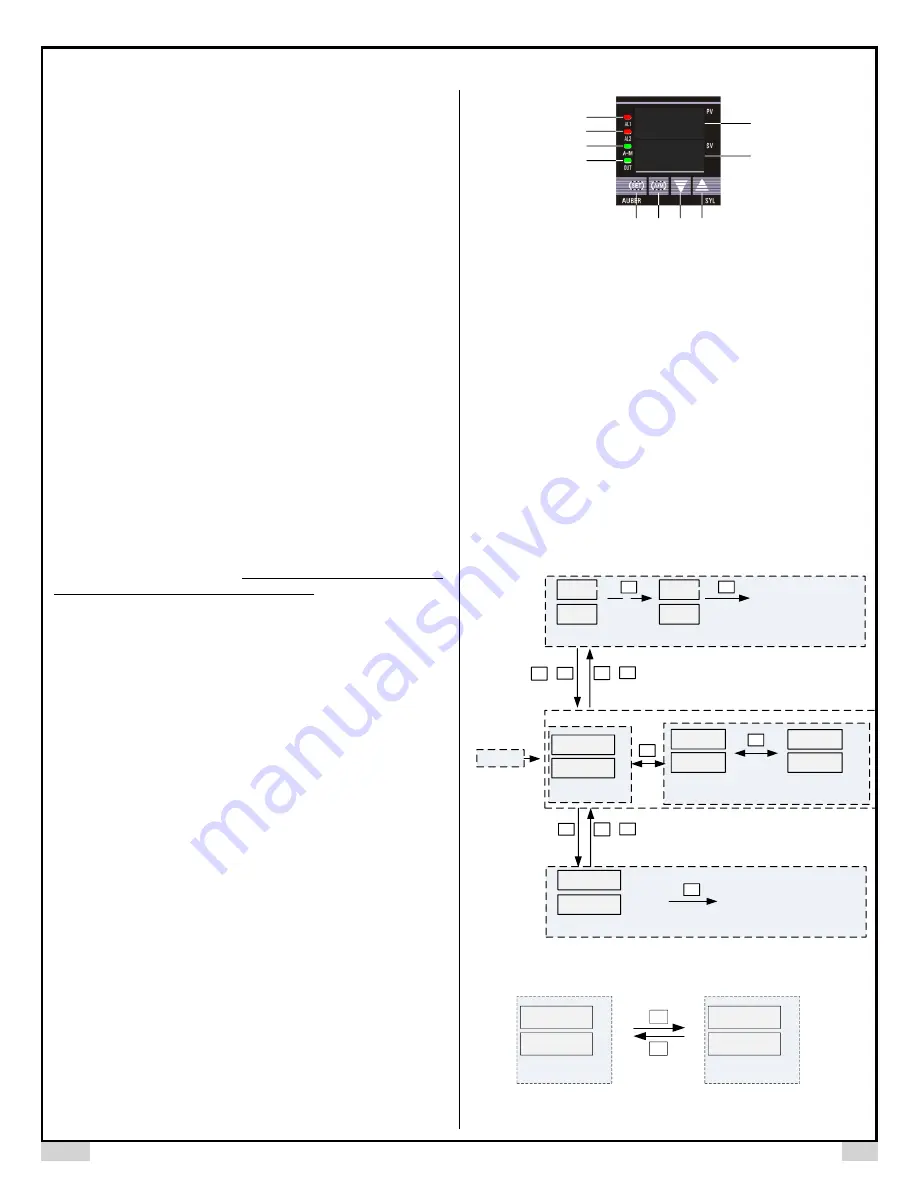
Figure 2. Front panel.
①
PV window: Displays the sensor readout/process value (PV), or parameter
/program name.
②
SV window: Displays the set value (SV), or parameter/program value.
③
AL1 indicator: It lights up when AL1 relay is on.
④
AL2 indicator: It lights up when AL2 relay is on.
⑤
A-M indicator: The light indicates the controller operating status. When A-M
is solid on, program is running. When A-M is flashing, program is paused.
When A-M is off, program is stopped.
⑥
Output indicator: It is synchronized with main control output and the power
to the load. When it is on, the heater (or cooler) is powered.
⑦
SET key: Press and hold for 3s to enter parameter settings. Press with A/M
key to enter ramp/soak program settings.
⑧
A/M key: Programming key; digit shift key.
⑨
DOWN key
▼
: Decreases numeric value of the setting value.
⑩
UP key
▲
: Increases numeric value of the setting value.
4.2.
Controller display mode
Power on
8
0
0
8
0
0
Display mode 1
800
P 4
Display mode 2: Step status
200
AL1 (high limit alarm)=200
Display mode 4: System Parameter Menu
3s
+
Next parameter
AL1
SET
SET
SET
A/M
PV
SV
0
Display mode 3: Ramp Soak Step Menu
Next step parameter
sec
SET
10
r01
SET
800
F 50
Step Segment 4
is current running.
+
SET
A/M
+
SET
A/M
3s
V
V
50: The time which current
step has run in minutes
Figure 3-1. Display mode 1-4
8
0
0
8
0
0
Display mode 1
PV
SV
A/M
3s
8 0 0
P 4
Display mode 5: Step Jump
PV
SV
A/M
3s
.
Decimal point on SV right
bottom corner is flashing.
Figure 3-2. Display mode 5, showing how to jump steps manually.


