AU SAE J1939 Скачать руководство пользователя страница 17


Au Group Electronics


Au SAE J1939 Simulator (Gen II) 2.00A User Manual Rev. D 


17

Table 4-1 

Function summary of step 1 control items 

Items 

Function 

Port 

Serial port can be selected from drop down list (COM1 to COM9) 

Connect 

Click “Connect” button to connect J1939 simulator with selected PC serial port. 

Disconnect 

Click “Disconnect” button to release the selected PC serial port. 

Exit 

Click “Exit” button to close the J1939 remote terminal program 

Product ID 

Display the current edition of J1939 simulator that’s hooked up with the serial port. (e.g. The 
demonstration in Figure 4-2 is a Vehicle Platinum Plus Edition) 

Simulator 
Version 

Display the current firmware version of J1939 simulator that’s hooked up with the serial port. (The 
demonstrated version of the connected simulator in Figure 4-2  is 0.2A) 

Product Serial 
Number  

Display the serial number of J1939 simulator that’s connected to the serial port. (The demonstrated 
serial number for the connected simulator in Figure 4-2  is 205) 

4.2. 

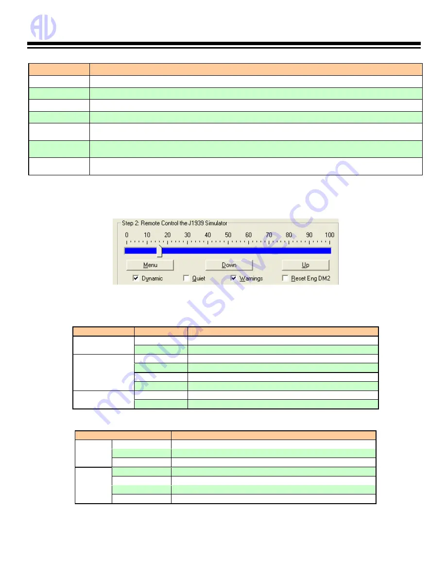
Step 2: Remote Control the J1939 Simulator 

Remote control includes a scale bar, 3 push buttons (

Menu

Down

Up

), and 4 check boxes (Dynamic, Quiet, Warnings, 

Reset Eng DM2) as shown in Figure 4-7. These tools are able to remote control the output/simulated signal of the Au 
J1939 Simulator 

PLUS

 editions. 


Figure 4-7 

PC remote terminal control panel step 2  

The scale bar represents the control step values from 0% to 100%. The sliding action can be made by 3 methods: 
keyboard, mouse or Down/Up buttons from remote terminal. They are summarized in Table 4-2 

Table 4-2 

Control methods for scale bar 


Action 

Function 

Left click 

Left click bring the slide to the desire location. 

Mouse 

Drag 

Click and hold left button drag the slide to desire location

 or 


Increase the scale range in 1 interval  

 or 


Decrease the scale range in 1 interval 

Pg Up 

Increase the scale range in 10 interval 

Keyboard 

Pg Dn 

Decrease the scale range in 10 interval 

“Down” button Decrease the scale range in 1 interval 

Remote terminal 

“Up” button 

Increase the scale range in 1 interval 

The functions for the 3 push buttons and 4 check boxes are listed in Table 4-3. 

Table 4-3 

Functions for push button and check boxes in step 2 

Tool 

Function 

Menu* 

Turn on/off warning (see 

note

 below) 

Down 

Decrease the control step value in 1 

Button 

Up 

Increase the control step value in 1 

Dynamic 

Switch between dynamic mode / static mode 

Quiet 

Turn on/off buzzer 

Warning 

Turn on/off Eng/ABS/Trans DM1 warnings & WIF indicator 

Check 

box 

Reset Eng DM2  Turn on/reset all Engine DM2 code 

*Note

: Menu button is active only in the 

Engine Premium Plus

 edition and 

Vehicle Platinum Plus

 edition. 

Содержание SAE J1939

Страница 1: ...or Gen II 2 00A User Manual Rev D Au Group Electronics May 2009 All copyrights are reserved by Au Group Electronics 1994 2009 This document can NOT be freely distributed without written approval from...

Страница 2: ...14 4 1 Step 1 Connect To J1939 Simulator 16 4 2 Step 2 Remote Control the J1939 Simulator 17 4 3 Display Panel Engine Idle Shutdown Is 18 4 4 Display Panel Engine Protection System EPS 18 4 5 Display...

Страница 3: ...tor is illustrated in Figure 1 3 Figure 1 3 Typical SAE J1939 15 network topology for Au J1939 Simulator s 1 2 Six Editions of Au SAE J1939 Simulators Six editions of Au SAE J1939 simulator Gen II 2 0...

Страница 4: ...ke and TVS Transient Voltage Suppressor protection on CAN bus Compact size 4 1 8 L X 1 3 4 W X 7 8 H Enclosure color Black or PC white Operating temperature 4 F to 185 F 20 C to 85 C Power supply 12V...

Страница 5: ...AE J1939 signal o Two modes can be switched easily Remote Terminal software available Plus editions only Display simulated J1939 signal on a computer screen All push button control functions are avail...

Страница 6: ...ission related signals o Engine Configurations 1 6 License Software Code Upgrade and Support Service License upgrading and annual service for the 6 editions of SAE J1939 Simulator are summarized in Fi...

Страница 7: ...Clock setup SPN 1605 1604 Cruise Light SPN 595 SAE J1939 Acknowledge protocol ACK NACK Engine Address Claimed Engine Address CANNOT Claim Response for Address Claim Request Address Conflict Response...

Страница 8: ...eset control Engine Red Stop Lamp On Off Engine Amber Lamp On Off Water In Fuel Indicator On Off Engine DM1 Single Packet warning Engine DM1 Multi Packet warnings Engine DM2 Single Packet warning Engi...

Страница 9: ...ton is pushed all data will stay at the last value Dynamic mode The value of all data will change automatically in SAE J1939 defined range Switch between dynamic mode and static mode press and hold bo...

Страница 10: ...the values of all J1939 signals A single press will increase all simulated data one step to next data level until they reach the maximum values 100 LED will be triggered on or off o If 100 LED is on p...

Страница 11: ...All SAE J1939 data can be changed within the SAE defined range from 0 to 100 control steps named 0 to 100 control step value from now on 6 LEDs are used to identify the control step value in the rang...

Страница 12: ...cates the data range from 61 to 79 Figure 3 5 Power Range 20 40 60 LED on indicating data range is from 61 to 79 o When control step value equals to 80 80 LED blinks o If keep pressing Up button the c...

Страница 13: ...utton until control step value 0 0 LED blink 4 Press Up button 100 LED on off 5 Continue press Up button for control step value 1 to 19 Power Range LED constant on 6 Continue press Up button for contr...

Страница 14: ...essage will pop up as shown in Figure 4 1 Figure 4 1 Warning message about minimum firmware requirement The Remote Terminal GUI Graphic User Interface includes a control panel and a display panel Cont...

Страница 15: ...ngine Premium Plus edition Engine Idle Shutdown IS Engine Protection System EPS Engine Info and Warning lamps Engine Basic Parameters A C Refrigerant Switch Engine DM1 and Engine DM2 are included ABS...

Страница 16: ...ow to use the GUI remote control of the J1939 Simulator Gen II 2 00A Plus editions 4 1 Step 1 Connect To J1939 Simulator Connect the simulator to power supply and a CAN network and then connect it to...

Страница 17: ...control the output simulated signal of the Au J1939 Simulator PLUS editions Figure 4 7 PC remote terminal control panel step 2 The scale bar represents the control step values from 0 to 100 The slidi...

Страница 18: ...le 5 3 in Chapter 5 Figure 4 9 Engine Protection System Display Panel EPS EN 1111 It is also named Engine Protection System Configuration which indicates the configuration disabled or enabled in calib...

Страница 19: ...rating the engine within the engine s safe operating range It indicates a condition when the over speed test input to the ECM is being driven Air Shutoff 2813 it indicates when the Air Shutoff driver...

Страница 20: ...nt temperature F Engine Coolant Pressure PSI Engine Coolant Level Battery voltage V Engine boost pressure PSI Actual Engine Torque EGR Mass Flow Rate Vehicle Identification Accelerator Position Engine...

Страница 21: ...d the Multi packets button will be active Figure 4 16 Click the button the whole list of engine DM1 will display Figure 4 17 If Engine DM1 warning is off a SAE defined non warning message will be show...

Страница 22: ...d set value 100 to activate Multi Packets of Engine DM1 Detail data information of engine DM1 multi packet is shown Table 4 4 to 4 7 Table 4 4 Engine DM1 Multi Packets 1 16 1 2 3 4 5 6 7 8 9 10 11 12...

Страница 23: ...102 102 102 102 102 102 102 102 102 102 102 FMI 16 17 18 19 20 21 22 23 24 25 26 27 28 29 30 31 OC 1 1 1 1 1 1 1 1 1 1 1 1 1 1 1 1 CM 0 0 0 0 0 0 0 0 0 0 0 0 0 0 0 0 4 12 Display Panel Engine Configu...

Страница 24: ...ing is on a Brake Switch signal low warning will be shown as 597 1 7 0 Figure 4 24 Figure 4 24 Display panel ABS DM1 4 14 Display Panel Transmission Dm1 Transmission DM1 is a single packet PGN If tran...

Страница 25: ...176 248 410 Exhaust Gas Temp F 459 4 44 371 3 786 7 1202 3154 9 Engine Trip mile 0 310 7 621 4 932 1 1242 7 621372 1 Total Vehicle Distance mile 0 621 4 1242 7 1864 1 2485 5 621372 1 Nominal Friction...

Страница 26: ...0 50 59 Engine Amber Red Stop High engine coolant temperature 110 0 60 Engine Amber High engine oil pressure 100 0 61 69 ABS Amber Brake switch short 597 1 70 80 ABS Amber Red Stop Brake switch short...

Страница 27: ...C2 Engine Percent Load At Current Speed 92 Actual Engine Percent Torque 513 61444 Electronic Engine Controller 1 EEC1 Engine Speed 190 Engine Exhaust Gas Recirculation Mass Flow Rate 2659 61450 Engine...

Страница 28: ...Cruise Control Vehicle Speed CCVS Cruise Control Active 595 Engine Fuel Rate 183 65266 Fuel Economy Liquid LFE Engine Instantaneous Fuel Economy 184 Engine Turbocharger Boost Pressure 102 Engine Intak...

Страница 29: ...77 7 155 3 6 160 6 3 5 005 354 5 4 321 25 50 6 24 5 8 375 5 4 22 2 9 4 1 5 2 9 5 128 5 4 5 4 5 3 4 22 25 6 376 4 62 1 124 3 5 128 5 2 9 004 375 5 3 240 88 37 5 4 68 4 06 396 5 2 8 27 4 2 03 2 8 1 1 2...

Страница 30: ...10 7 015 144 9 14 1124 38 175 21 83 20 3 165 8 14 23 10 15 14 5 25 10 1 17 449 75 14 17 15 7 10 5 14 23 10 4 168 7 217 5 435 17 449 75 10 1 014 165 8 13 1044 13 162 5 20 27 18 56 186 8 12 8 17 6 9 28...

Страница 31: ...76 7 31 803 15 18 025 4 24 1927 63 300 37 43 34 8 11 2 24 68 17 4 24 9 17 4 30 771 05 24 30 27 18 24 68 46 4 39 372 8 745 6 30 771 05 17 4 024 11 2 23 1847 25 287 5 35 87 33 06 18 4 22 8 62 6 16 53 22...

Страница 32: ...4 43 1124 45 25 2 035 68 34 2730 75 425 53 03 49 3 60 8 34 113 24 65 34 12 75 24 6 42 1092 3 34 42 38 2 25 5 34 113 82 4 246 6 528 2 1056 3 42 1092 3 24 6 034 60 8 33 2650 5 412 5 51 47 47 56 53 6 32...

Страница 33: ...1 699 1398 1 56 1445 7 32 5 045 140 44 3534 550 68 62 63 8 132 8 44 158 31 9 44 16 5 31 9 55 1413 6 44 55 49 5 33 44 158 118 4 454 3 683 5 1367 55 1413 6 31 9 044 132 8 43 3453 63 537 5 67 06 62 06 12...

Страница 34: ...68 1767 39 7 055 212 54 4337 13 675 84 22 78 3 204 8 54 203 39 15 54 20 25 39 1 67 1734 85 54 67 60 7 40 5 54 203 154 4 662 838 9 1677 7 67 1734 85 39 1 054 204 8 53 4256 88 662 5 82 66 76 56 197 6 52...

Страница 35: ...90 5 1009 7 2019 5 81 2088 25 47 065 284 64 5140 38 800 99 82 92 8 276 8 64 248 46 4 64 24 46 4 80 2056 15 64 80 72 48 64 248 190 4 869 7 994 2 1988 4 80 2056 15 46 4 064 276 8 63 5060 787 5 98 25 91...

Страница 36: ...2330 1 93 2409 55 54 2 075 356 74 5943 5 925 115 41 107 3 348 8 74 293 53 65 74 27 75 53 6 92 2377 4 74 92 83 2 55 5 74 293 226 4 1077 3 1149 5 2299 1 92 2377 4 53 6 074 348 8 73 5863 25 912 5 113 85...

Страница 37: ...87 6 1690 2 156275 1 157207 1 106 2730 8 61 5 085 1082 7 84 6746 75 200799 8 131 01 121 8 944 5 84 338 60 9 84 42 60 9 105 2698 7 84 105 131 217 7 84 338 280 4 1592 5 125268 6 126262 8 105 2698 7 60 9...

Страница 38: ...368 6 2666 7 466339 8 466650 5 118 3052 1 68 7 095 2464 2 94 7549 88 700299 3 146 6 136 3 2326 94 383 68 15 94 1321 1 68 2 117 3019 95 94 117 233 6 612 1 94 383 361 4 2569 435333 3 435706 1 117 3019 9...

Страница 39: ...nal V1 00A will be provided when Au SAE J1939 Simulator is ordered 3 A PC equipped with serial port with a serial extension cable 4 Or a PC equipped with USB port plus a USB to Serial Converter A 2 St...

Страница 40: ...enu Folder window pop up use the default folder and click Next to continue Figure A 6 Figure A 6 Figure A 7 7 Select Additional Tasks window pop up check both Create a desktop icon and Create a Quick...

Страница 41: ...PC equipped with USB port and a USB to Serial Converter B 2 Step by Step License management Toolset Installation Note For any user had the License management Toolset installed on your PC before please...

Страница 42: ...and Create a quick launch icon then click next Figure B 6 7 Ready to Install window shows up click Install as shown in Figure B 7 Figure B 6 Figure B 7 8 Wait until Completing Au J1939 Simulator Lice...

Страница 43: ...t Product ID showing Engine Basic in this demonstration Figure B 10 Note Each Au J1939 Simulator will have a unique Serial Number and may have a different Product ID J1939 Simulator Edition 2 Enter a...

Страница 44: ...button Figure B 13 Engine premium is demonstrated here Figure B 13 Engine premium license validate 5 When it is updated successfully a beep will be heard And Au J1939 Simulator License Toolset will s...

Страница 45: ...SAE J1939 simulator etc C 2 How to Install Au PIC Bootloader Note If the Au PIC Bootloader has been installed on PC before please bypass step 1 to step 8 and start with step 9 1 Double click icon of t...

Страница 46: ...e C 6 Figure C 6 Figure C 7 7 Ready to Install window shows up Click Install Figure C 7 8 After a few seconds Completing the Au PIC Bootloader Setup Wizard window shows up check launch Au Bootloader c...

Страница 47: ...Bootloader mode Software Trigger Method Connect 9 12V DC power supply to Au J1939 Simulator at the BUS side then click Reset PIC button on Au PIC Bootloader User Interface Figure C 12 Warning LED will...

Страница 48: ...take a few minutes depending on the file size and communication speed When programming finished click exit to exit Bootloader mode Figure C 15 The Au J1939 Simulator should function normally with the...

Отзывы: